RF Module

Optimize Microwave and Millimeter-Wave Devices

The RF Module helps you optimize designs by investigating effects such as electromagnetic wave propagation and resonance effects in high-frequency applications. Use the RF Module for understanding and predicting the performance of devices used in the RF, microwave, and millimeter-wave industries.

Designers of RF and microwave devices need to ensure that the electromagnetics-based products are reliable and robust. Traditional electromagnetics modeling lets you examine electromagnetic wave effects alone, but no real-world product operates under ideal operational conditions. To see how other physics phenomena affect the design, you need multiphysics modeling, which allows extending your analysis to include effects such as temperature rise and structural deformations.

With the RF Module add-on to the COMSOL Multiphysics® simulation platform, you can analyze RF designs in ideal or multiphysics scenarios, including microwave and RF heating, all within the same software environment.

Contact COMSOL
A car model in the Thermal Wave color table enclosed in a dome-like anechoic chamber.

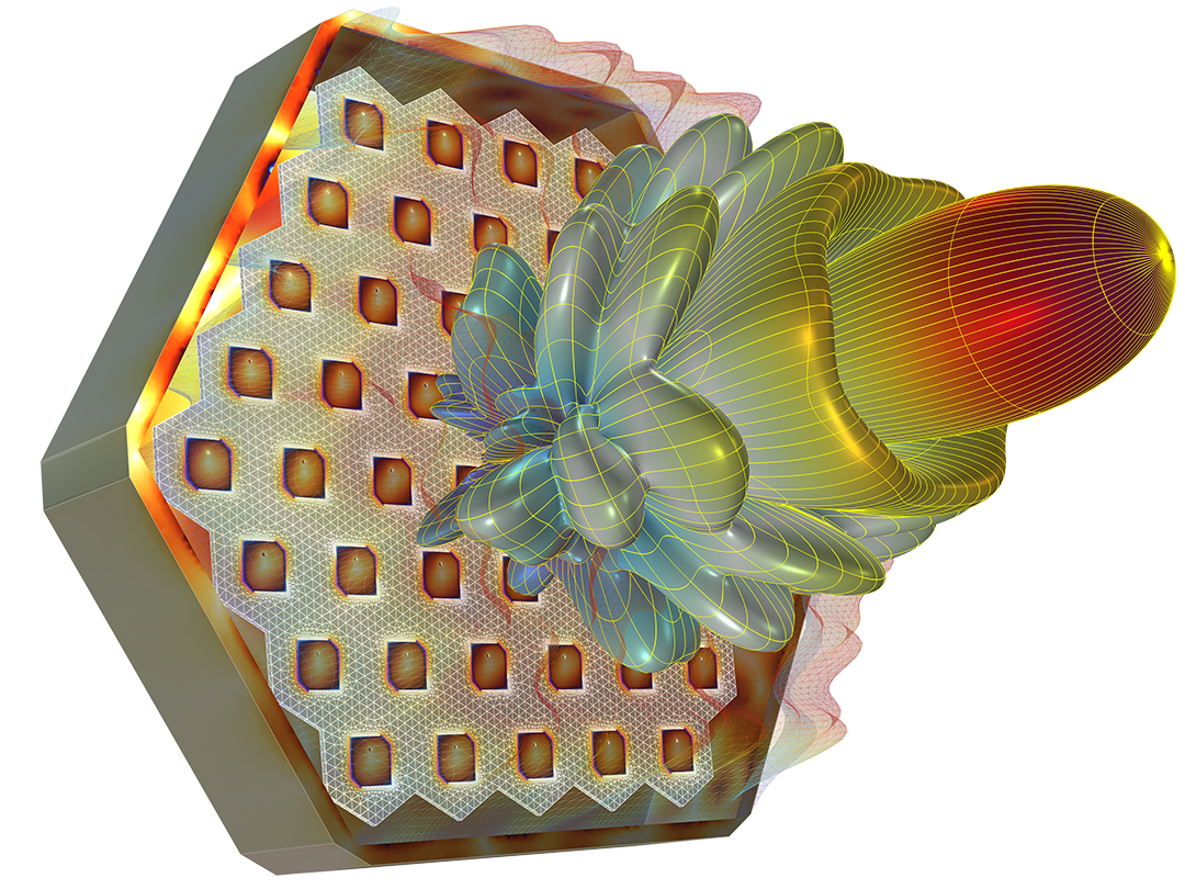
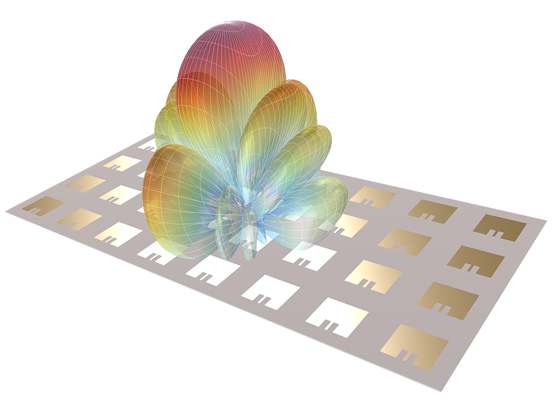
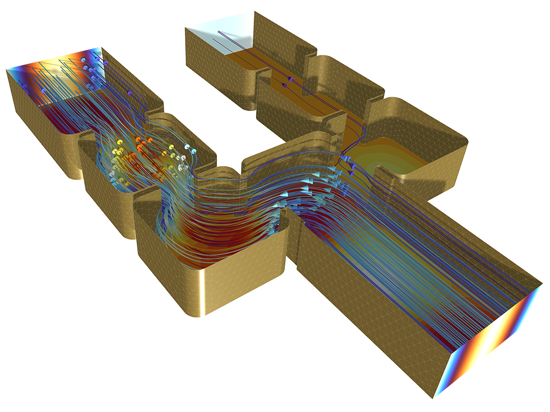
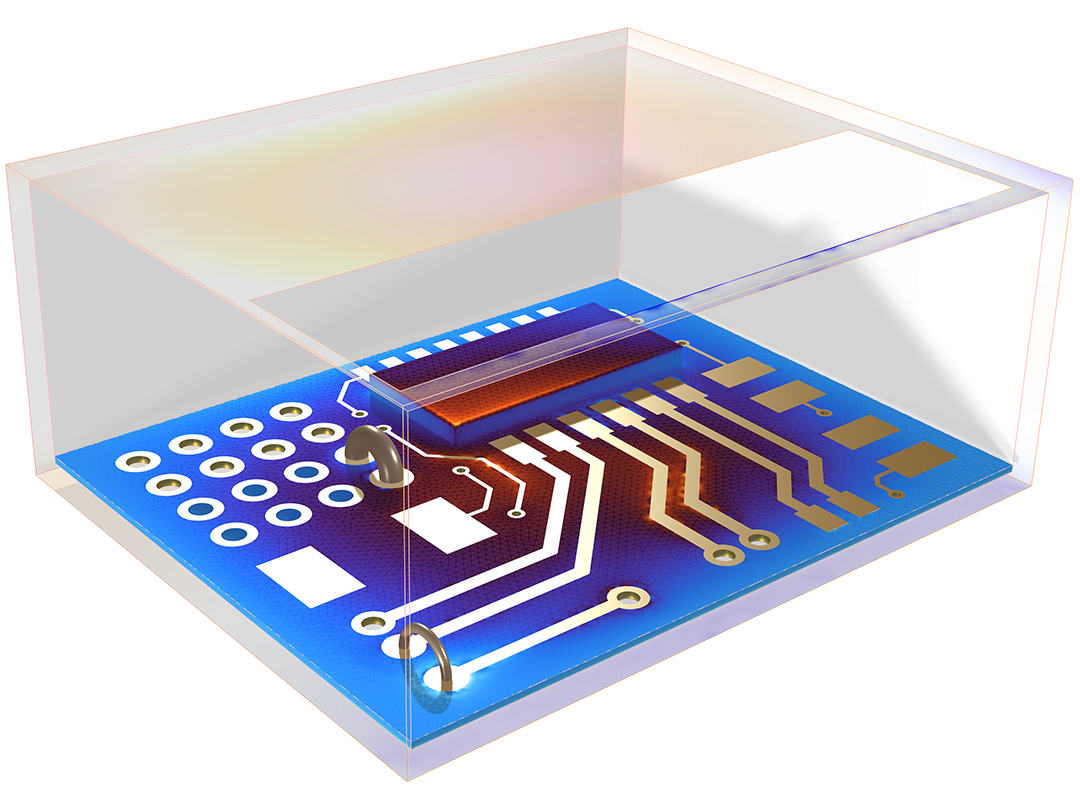
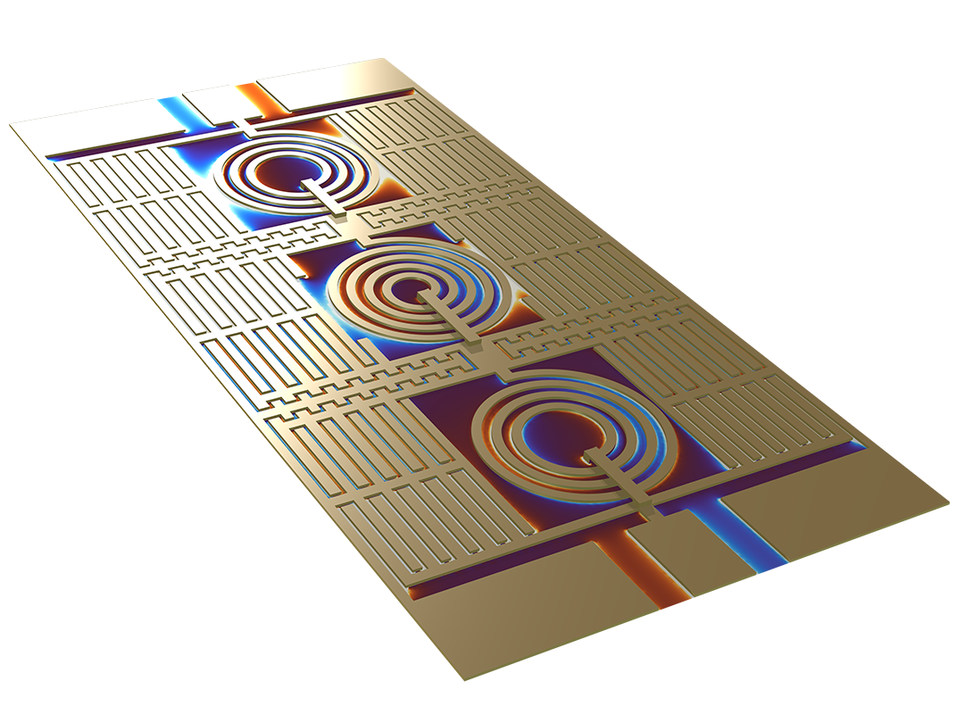
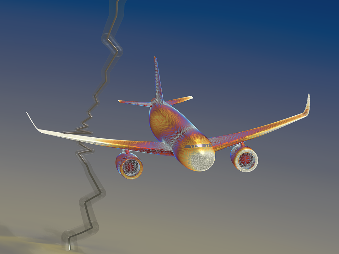
Design for the Present and Future with the RF Module

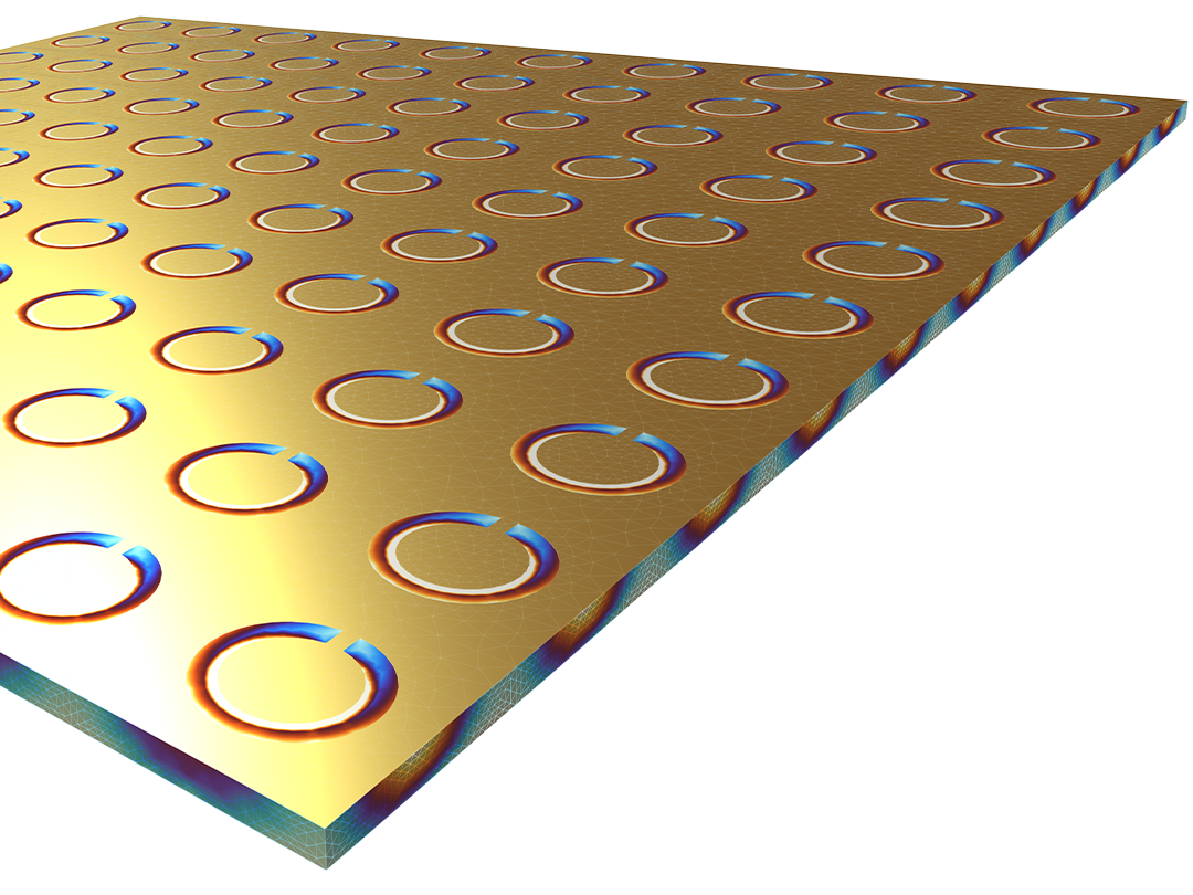
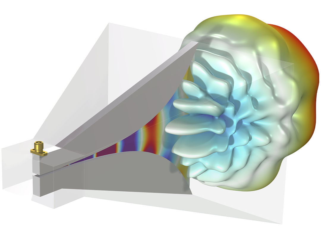
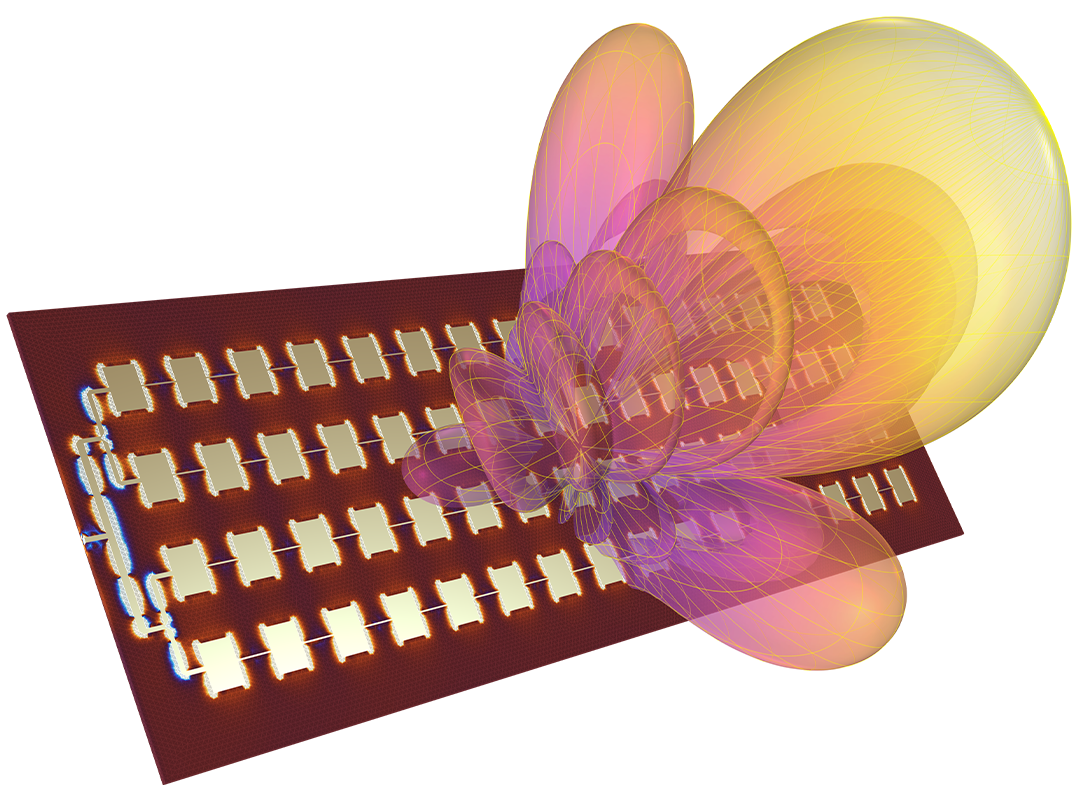
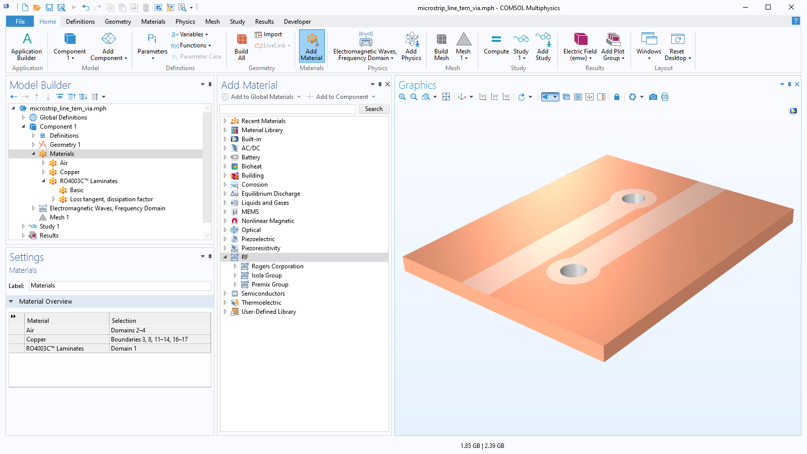
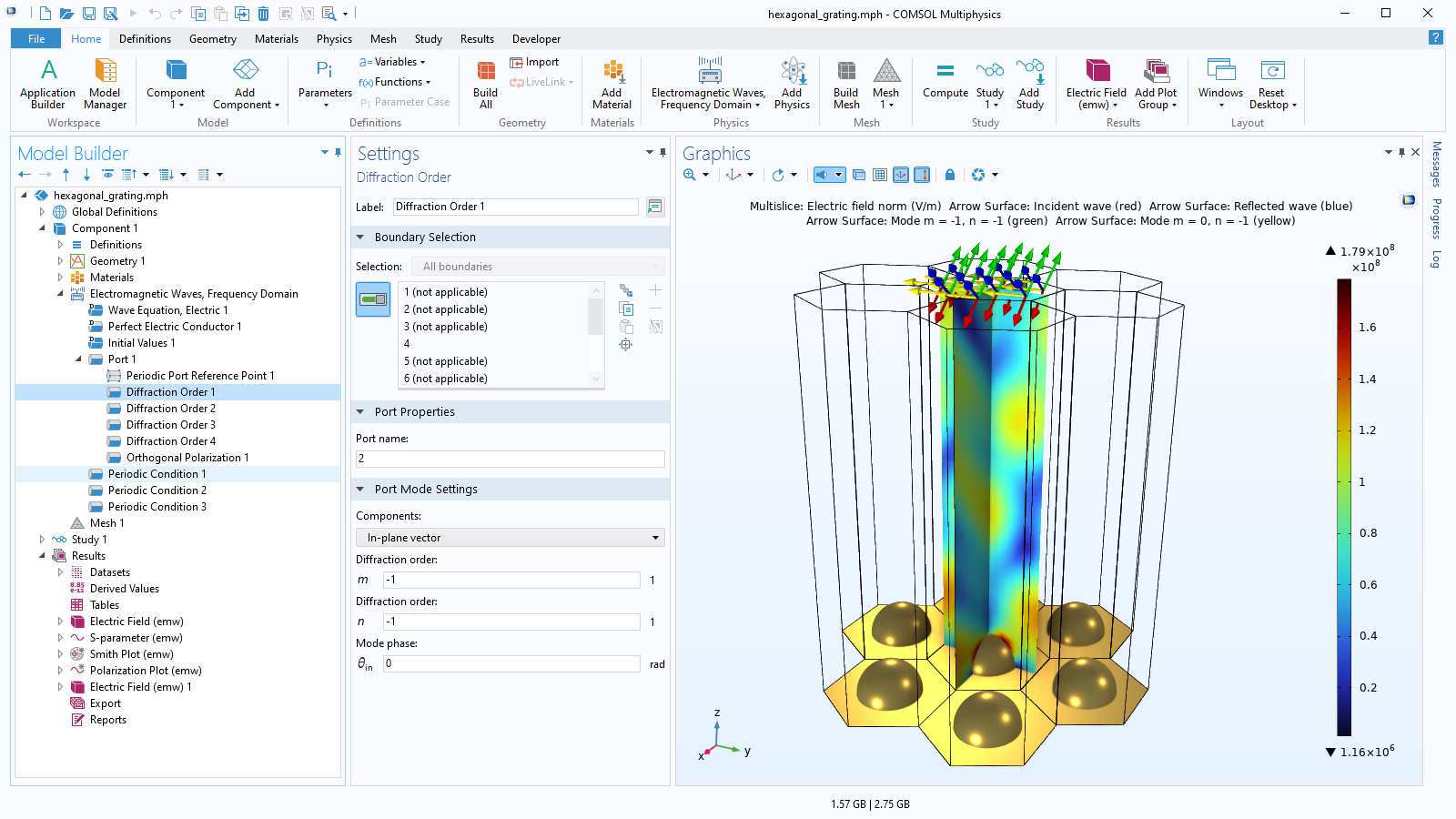
In the fast-paced industry of wireless devices, electromagnetic wave analysis is used in product development to keep up with advancements in technology. For example, antennas and RF front ends, including filters, couplers, power dividers, and impedance matching circuits, should be compatible with future developments, such as the 5G MIMO network, internet of things (IoT), and SatCom.

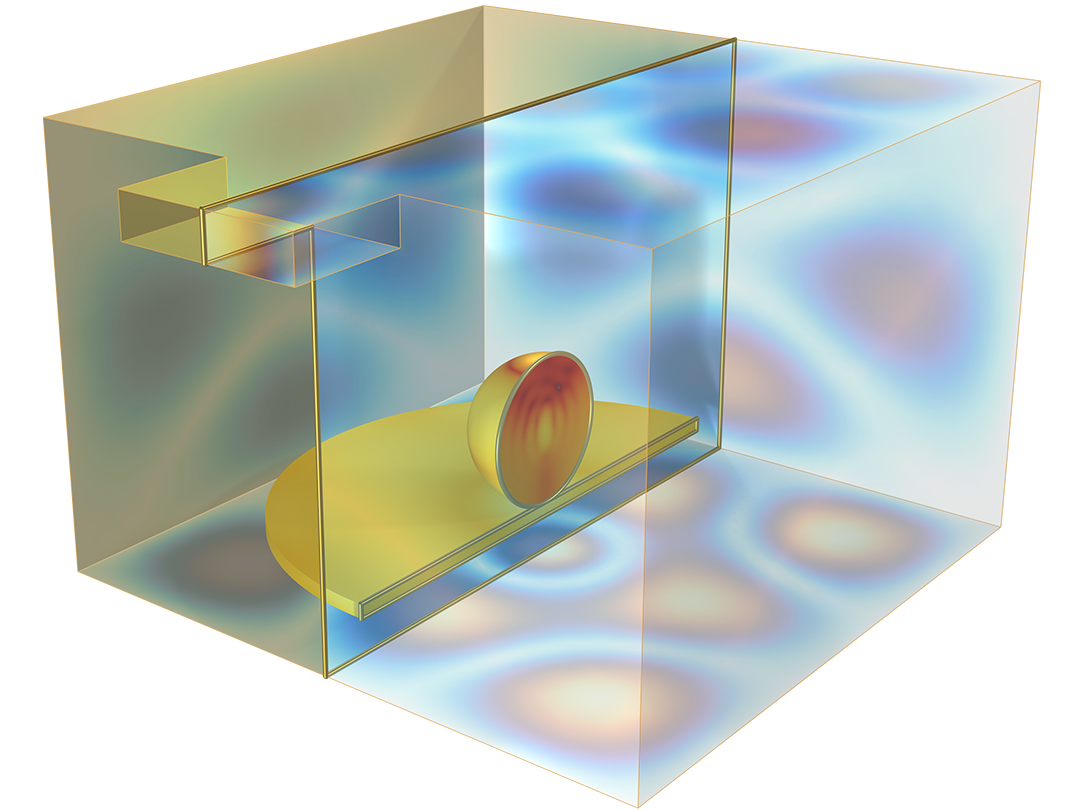
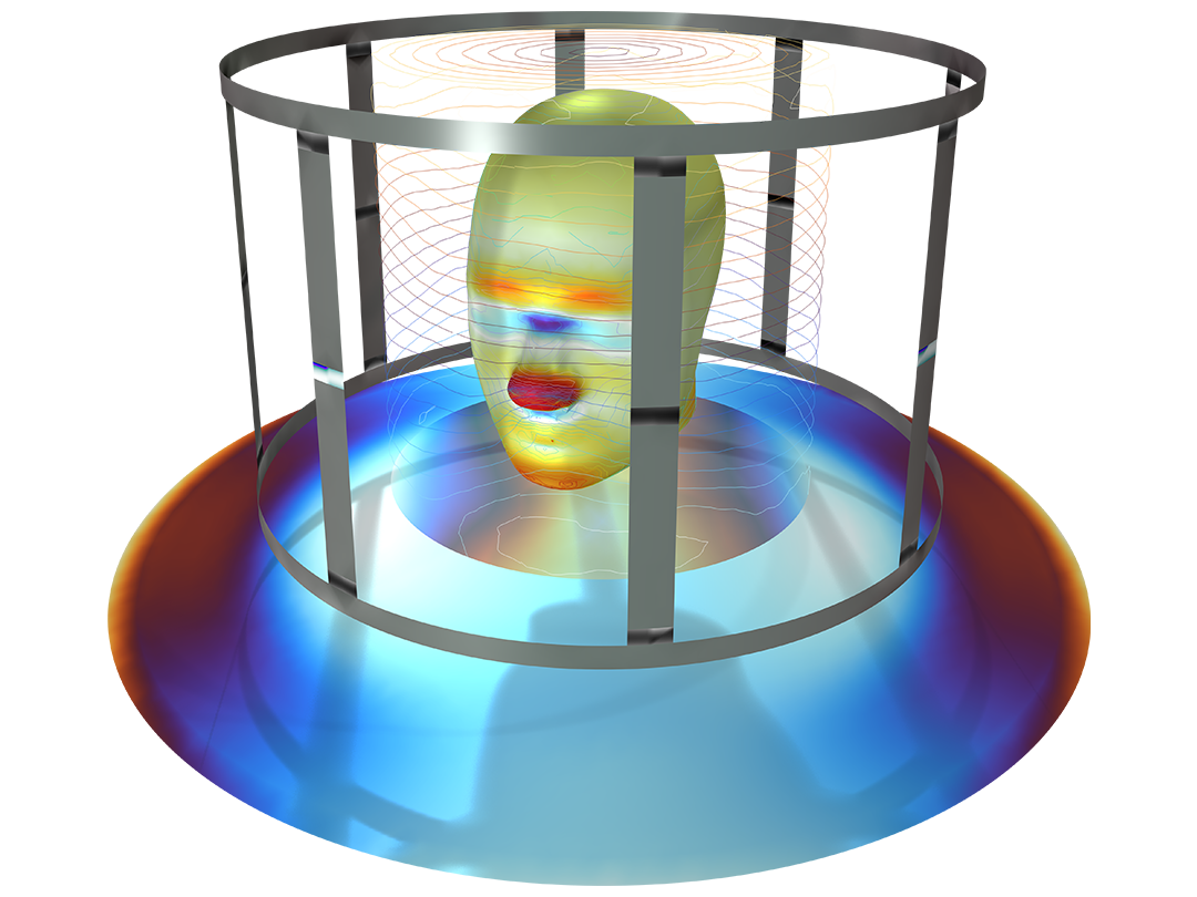
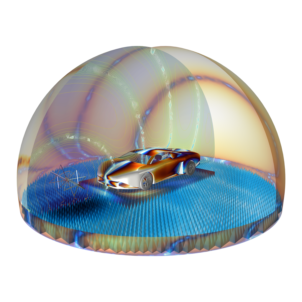
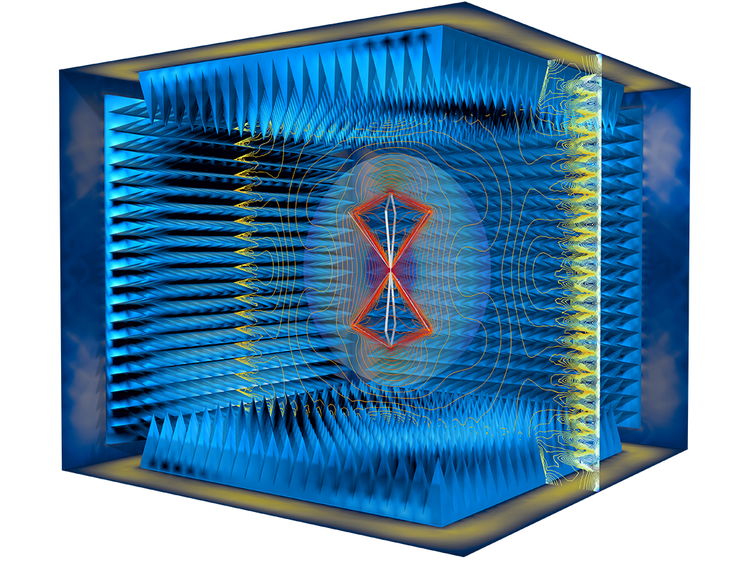
It is also important to use analysis software to evaluate RF interference and compatibility in wireless communication platforms for the seamless operation of your products for developing applications, including wearable devices, autonomous vehicles, and state-of-the-art microwave and RF products.

High-Frequency Electromagnetics Analyses and Solvers

The RF Module relies heavily on the proven finite element method (FEM) for standard high-frequency electromagnetics analyses, and also includes alternate methods and solvers for specific types of analysis. The default solvers built into the RF Module help you feel confident that your analysis is correct and the design is backed up by solid numerical solutions. FEM is used for frequency-domain and transient analysis, with vector/edge elements of order 1, 2, or 3 that adapt to the curvature of CAD surfaces. There are tetrahedral, hexahedral, prismatic, and pyramidal mesh elements, as well as automatic and adaptive meshing.

For frequency-domain analysis, you can compute resonance frequencies, S-parameters, near/far fields, Q factors, propagation constants, and antenna characterization through frequency sweeps. The computation efficiency can be boosted by using model order reduction (MOR) techniques such as modal method and adaptive frequency sweeps based on the asymptotic waveform evaluation (AWE) method. For transient analysis, you can model nonlinear materials, signal propagation and return time, very broadband behavior, and time-domain reflectometry (TDR).

Additional methods and analyses are available for transmission line equations, explicit time domain, electric circuit modeling using netlist, asymptotic scattering, and the boundary element method (BEM).

What You Can Model with the RF Module

Perform various radiofrequency analyses with the COMSOL® software.

A close-up view of a microstrip patch antenna model showing the far-field radiation pattern.

Antennas and Antenna Arrays

Compute reflected power and far-field radiation and gain patterns for antenna arrays.

A close-up view of a waveguide diplexer model showing the electric field and power flow.

Transmission Lines and Waveguides

Analyze microstrip lines, coplanar waveguides (CPW), and substrate integrated waveguides (SIW).

A closeup view of a Wilkinson power divider model showing the electric field.

Couplers and Power Dividers

Compute S-parameters for analyzing matching, isolation, and coupling performance for couplers and power dividers.

A closeup view of a circuit board model showing the electric field.

EMI/EMC Applications

Analyze electromagnetic interference (EMI) and electromagnetic compatibility (EMC), including crosstalk and isolation.

A closeup view of a microstrip line circulator model.

Ferrimagnetic Devices

Include magnetic materials in microwave components such as ferrite resonators and circulators.

A close-up view of an RFIC low-pass filter model with a coplanar waveguide.

Filters

Analyze the performance of microstrip, CPW, and cavity filters, including thermal, structural, and other physical phenomena.

A closeup view of a microwave oven model showing the heat distribution within.

Microwave Ovens

Combine full-wave electromagnetics analysis with time-dependent heat transfer simulations.

A close-up view of an MRI birdcage model showing the electric field.

Biomedical and MRI

Simulate microwave treatment as well as MRI interaction with implanted devices.

A closeup view of a PEC sphere model showing the RCS and background field.

Scattering and RCS

Calculate radar cross section (RCS) and general scattering fields using full-wave and asymptotic methods.

A closeup view of a split ring resonator model showing the electric field on one ring.

Frequency-Selective Surfaces

Model transmission, reflectance, and diffraction of frequency selective surfaces and general periodic structures.

A close-up view of an airplane model showing the electric field.

ESD and Lightning

Address time-varying high-voltage sources and their impact on circuits and airplanes.

RF and Microwave Heating

Microwave heating is important in food processing, medical technology, and of course in mobile devices. The latest 5G components generate more heat than previous generations of devices, making thermal management more important than ever. The RF Module has fully integrated electromagnetic heating and heat transfer functionality, with the capability of handling conduction, convection, and temperature-dependent material data. Together with the Structural Mechanics Module or MEMS Module, you can account for thermal deformation and stresses. By adding the Heat Transfer Module, you can further include the effects of thermal radiation in your models.

Antennas and Radiation

You can readily characterize the performance of radiating elements, such as antennas or antenna arrays, in terms of directivity and gain from its radiation pattern, which is calculated from the near-field solution using a specialized far-field analysis. Antenna input matching properties are readily available by the use of port conditions on the antenna feed, which is used to calculate S-parameters.

In the case where a radiating device has cylindrical symmetry, a 2D axisymmetric analysis option enables orders of magnitude faster computations.

Antenna array analysis is computationally demanding if modeled explicitly. For a quick feasibility study of an antenna array’s performance, you can simplify the simulation by using the functionality for antenna array factors and thereby saving precious computation time.

For scattering simulations, a dedicated scattered-field formulation allows you to specify an incident wave as a background field including Gaussian beam, linearly polarized plane wave, and user-defined fields.

The inclusion of perfectly matched layers (PMLs) enables absorption of outgoing radiation for a wide range of frequencies and incidence angles.

Features and Functionality in the RF Module

Explore the features and functionality of the RF Module in more detail in the sections below.

A closeup view of the Model Builder with the Electromagnetic Waves, Frequency Domain node highlighted and a dipole antenna model in the Graphics window.

Built-In User Interfaces

The RF Module provides built-in user interfaces for all of the analysis types listed above. These interfaces define sets of domain equations, boundary conditions, initial conditions, predefined meshes, predefined studies with solver settings, as well as predefined plots and derived values. All these steps are accessed within the COMSOL Multiphysics® environment.

The boundary conditions available all correspond to the microwave components being modeled. Part libraries aid in building the geometry of the component. Meshing and solver settings are handled automatically by the software, with options for manual editing.

A closeup view of the Loaded Part settings and a Wilkinson power divider model in the Graphics window.

CAD Import and Part Libraries

With the addition of the CAD Import Module, you can import a variety of industry-standard CAD formats for your RF analysis. The import options include repair and you can defeature your geometry to prepare it for meshing and analysis. The Design Module includes these features, plus the following 3D CAD operations: loft, fillet, chamfer, midsurface, and thicken.

When building geometries directly in COMSOL Multiphysics®, the RF Module includes a Part Library that contains complex shapes frequently required for RF simulations: connectors, surface-mount devices, and waveguides. The parts are available as parametric geometry models and many of the RF parts include selections for the conductive boundary for applying PEC boundary conditions while setting up the analysis.

A closeup view of the Model Builder and a 1D plot in the Graphics window.

Frequency- and Time-Domain Transformations

While transient analyses are useful for TDR to handle signal integrity (SI) problems, many RF and microwave examples are addressed using frequency-domain simulations that generate S-parameters. By performing the frequency-to-time fast Fourier transform (FFT) after the conventional frequency domain study, TDR analysis is feasible. This type of analysis helps in identifying physical discontinuities and impedance mismatches on a transmission line by investigating the signal fluctuation in the time domain.

Performing a wideband frequency sweep with a small frequency step size could be a time-consuming and cumbersome task. A wideband antenna study, such as an S-parameter and/or far-field radiation pattern analysis, can be obtained by performing a transient simulation and a time-to-frequency FFT.

A closeup view of the Model Builder with the Thermal Expansion node highlighted and a cavity filter model in the Graphics window.

Multiphysics Analysis

For modeling real-world phenomena, COMSOL Multiphysics®, the RF Module, and other add-on products allow for a variety of multiphysics analyses. Thermal analysis and stress deformation are important considerations for filter designs. For example, cavity filters are typically made out of both dielectric and metallic materials. The conductivity of metals varies with temperature, which affects the losses in the device and dissipates heat. The dissipation of heat leads to a rise in temperature, and a variation in temperature will cause materials to expand or contract. Thus, when a cavity filter undergoes a high power load or an extreme thermal environment, drift may occur. Multiphysics analysis will help you consider such effects in device optimization.

A closeup view of the Model Builder with the Perfectly Matched Layer node highlighted and a human head geometry next to an antenna in the Graphics window.

Boundary Conditions

For accurate high-frequency electromagnetics modeling, you need access to extensive options for boundary conditions, such as to describe metallic boundaries, for instance.

Notable boundary conditions in the RF Module:

  • Perfect electric and magnetic conductor (PEC and PMC)
  • Impedance (finite conductivity)
  • Transition (thin lossy metallic sheet and multiple layers)
  • Periodicity (Floquet)
  • Absorbing boundaries
  • Capacitive, inductive, and resistive lumped elements
  • Ports
    • Rectangular and circular waveguide
    • Coaxial cable
    • Numeric (mode matched on an arbitrary shape)
    • Transverse electromagnetic (TEM)
    • Lumped
    • Two- and three-port network systems with Touchstone files
A closeup view of the Model Builder with the Materials node highlighted and the Add Material window showing the RF options.

Material Properties

The RF Module includes a library with material properties for substrate materials to assist in modeling RF, microwave, and millimeter-wave circuit boards as well as for nonlinear magnetic modeling. The RF material library contains the material property data from the following companies’ products:

  • Rogers Corporation
  • Isola Group
  • Avient Corporation

For advanced modeling, you can customize the material by specifying properties for inhomogeneous, anisotropic, nonlinear, and dispersive materials. All properties can be spatially varying and discontinuous. Additionally, you can define the relative permittivity and permeability. For lossy materials, you can use complex-valued properties, conductivity, or loss tangents. For materials exhibiting dispersive materials, two models are provided: Drude–Lorentz and Debye. For more advanced analysis involving magnetic materials, you can specify a nonlinear magnetic behavior.

A closeup view of the Model Builder with the Smith Plot node highlighted and the corresponding results in the Graphics window.

Data Visualization and Extraction

Present simulation results using predefined plots of electric and magnetic fields, S-parameters, power flow, dissipation, far-field radiation patterns, and Smith plots. S-parameters can be exported to the Touchstone file format. You can also display your results as plots of expressions of the physical quantities that you define freely, or as tabulated derived values obtained from the simulation.

A closeup view of the Model Builder with the Diffraction Order node highlighted and a hexagonal grating model in the Graphics window.

Periodic Structures

Periodic structures are fundamental to many engineered electromagnetic structures being developed for applications such as novel 5G hardware, subwavelength imaging, and advanced radar technologies. In the RF Module you can model these structures, including their high-order diffraction modes, with Floquet periodic conditions and varying diffraction orders. Using these features, elements for reflect- and transmitarrays and holographic surfaces can be accurately designed.

Every business and every simulation need is different.

In order to fully evaluate whether or not the COMSOL Multiphysics® software will meet your requirements, you need to contact us. By talking to one of our sales representatives, you will get personalized recommendations and fully documented examples to help you get the most out of your evaluation and guide you to choose the best license option to suit your needs.

Just click on the "Contact COMSOL" button, fill in your contact details and any specific comments or questions, and submit. You will receive a response from a sales representative within one business day.

Next Step

Request a Software Demonstration