support@comsol.com
Multibody Dynamics Module Updates
For users of the Multibody Dynamics Module, COMSOL Multiphysics® version 6.2 introduces new functionality for modeling electric motors and generators, the option to add radial constraints to planar joints, and a new feature for running static analyses of unconstrained structures. Browse these updates and more below.Multiphysics Interface for Modeling Magnetic–Structure Interaction in Rotating Machinery
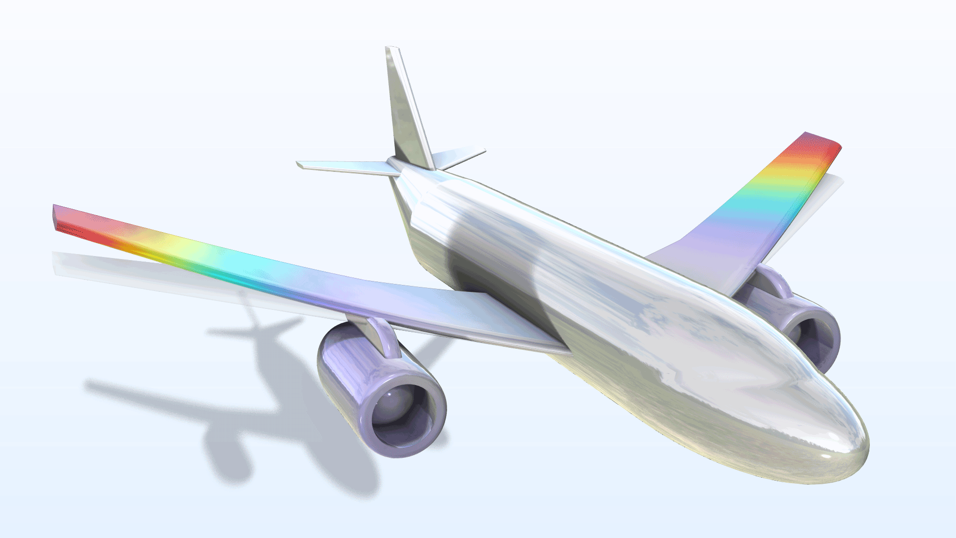
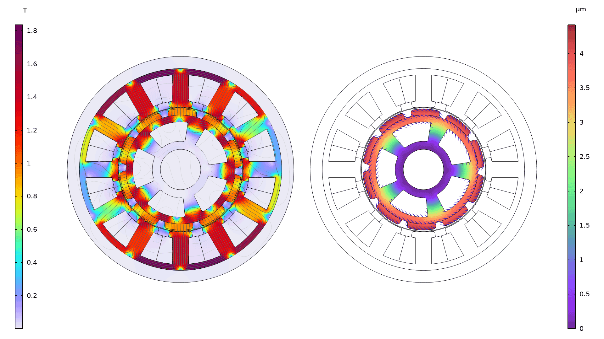
A new Magnetic-Rigid Body Interaction in Rotating Machinery multiphysics interface sets up the coupling needed to study structural mechanics and rigid body dynamics in rotating electromagnetic motors and generators. This interface combines a Multibody Dynamics interface with a Rotating Machinery, Magnetic interface through the new Magnetic Forces, Rotating Machinery multiphysics coupling. The coupling connects the structural and electromagnetic physics at the domain level and adds the loading on a rotating structure that is rigid or deformed due to Maxwell stresses. This functionality can be used to compute how deformations and stress originating from air gap forces are distributed in both the stator and the rotor of an electric motor. (Application examples include magnetic bearings and unbalanced rotors.) You can view this interface in the new Magnetic–Structure Interaction in a Permanent Magnet Motor tutorial model. Note that this feature requires the AC/DC Module.
Radial Constraints in Planar Joints
For planar joints, the Constraints feature includes a new option to add radial constraints, where the center and radius of the constraint circle can be set. With this option, a radial constraint is applied on the planar motion of a body, which is similar to placing an imaginary stopper circle that restricts the motion of the body to the radial direction.
Inertia Relief Analysis
Inertia relief analysis is a special type of static analysis for unconstrained structures that are accelerated by external loads, where the external loads and inertial forces of the structure must maintain a dynamic force balance. In all of the Structural Mechanics interfaces, a new Inertia Relief feature has been added. This feature can be used to automate the setup of a special study sequence that computes the acceleration field, the corresponding inertia forces, and the resulting stresses.
Embedded Reinforcements
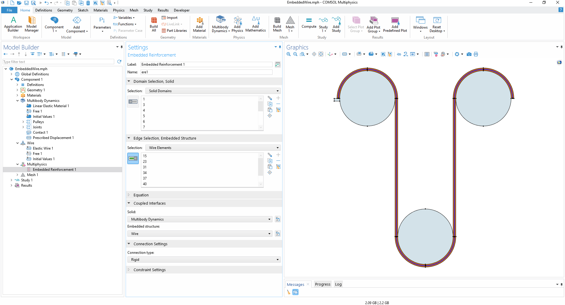
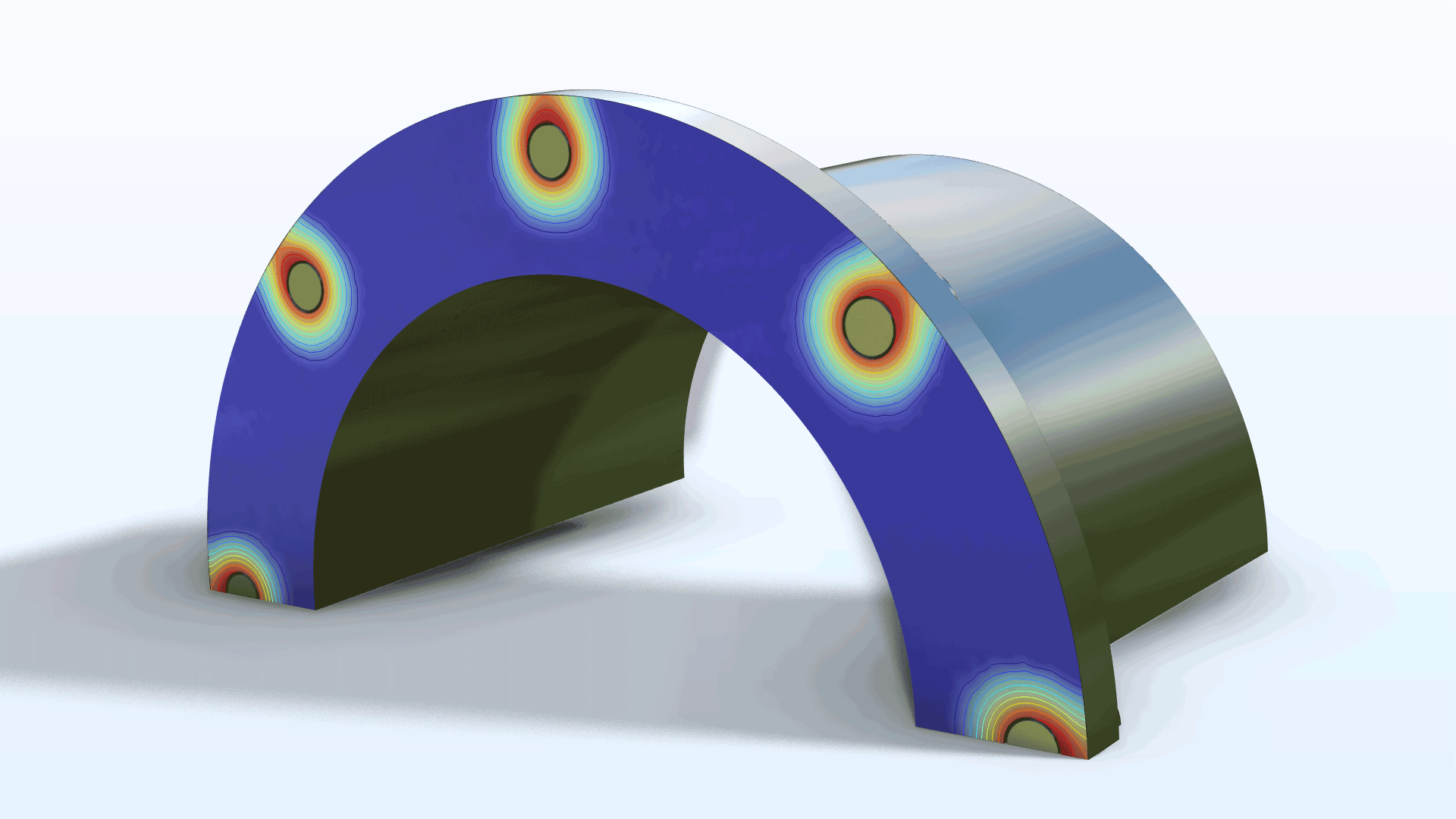
When using the Embedded Reinforcement multiphysics coupling, it is now possible to embed elements from a Wire interface into a flexible solid domain to act as reinforcements. Additionally, with a license for the Structural Mechanics Module, it is also possible to insert edge elements from the Truss or Beam interfaces and surface elements from the Membrane interface into a domain modeled with the Multibody Dynamics interface. This new functionality is useful when modeling structures like wire-stiffened belt drives, for example. It can also be used to model debonding between the embedded element and the surrounding solid, where the connection can either be fully rigid or flexible.
Unconstrained Structures When Modeling Contact
Contact problems often involve insufficient constraints until contact has been established. As a result, the stiffness matrix becomes singular. A new Stabilization feature has been added to alleviate this inherent difficulty.
Limited Displacement
The possibility to prescribe a limited displacement (that is, the maximum distance that a point, edge, or boundary can move in a certain direction) has been added to the Solid Mechanics, Multibody Dynamics, Shell, Layered Shell, and Membrane interfaces. This functionality can be viewed as a simplified version of contact analysis, where no second object is needed to stop the movement. In previous versions, this functionality was only available in the edge-type interfaces, such as Beam or Truss, and therefore was only applicable to edges or points.
New Tutorial Models
COMSOL Multiphysics® version 6.2 brings two new tutorial models to the Multibody Dynamics Module.
Magnetic–Structure Interaction in a Permanent Magnet Motor
Application Library Title:
pm_motor_2d_structure_interaction
Download from the Application Gallery
Dynamics of a Hopping Hoop
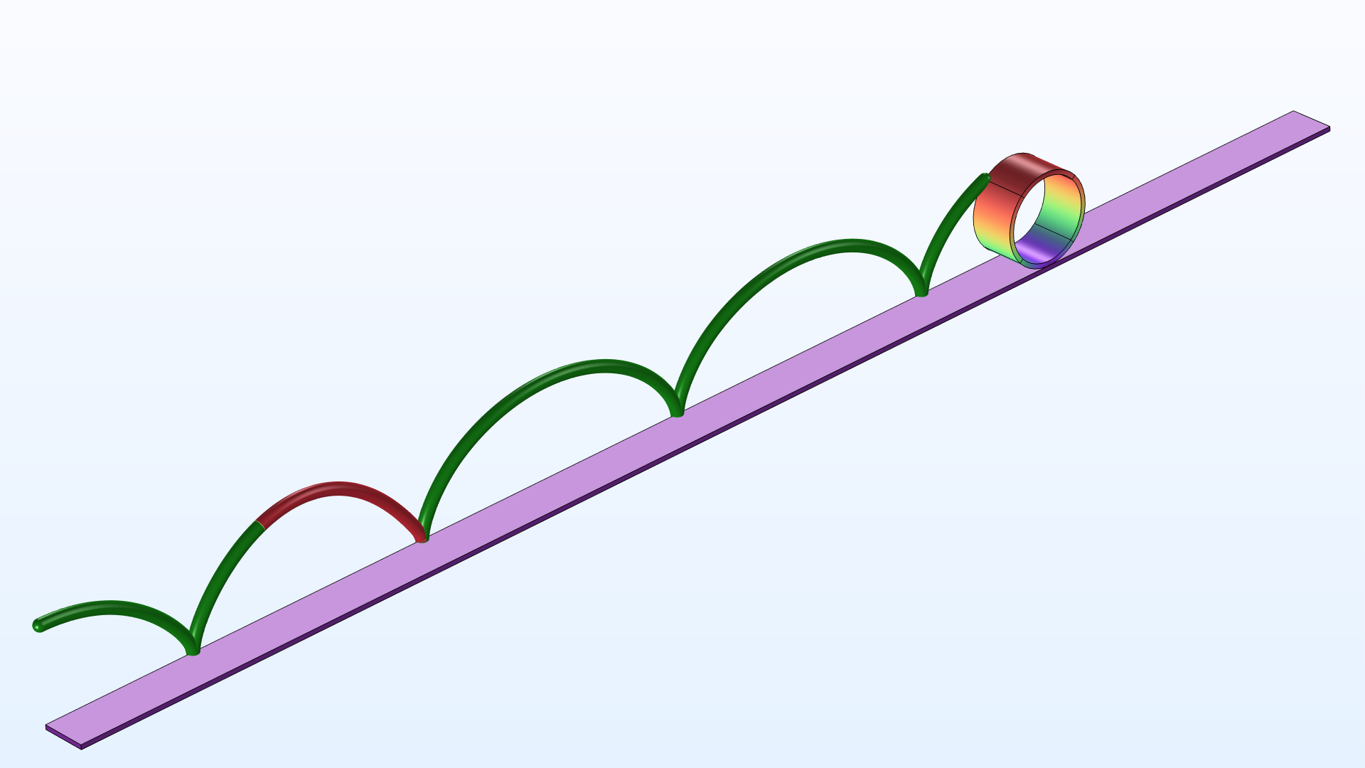
Application Library Title:
hopping_hoop
Download from the Application Gallery