support@comsol.com
AC/DC Module Updates
For users of the AC/DC Module, COMSOL Multiphysics® introduces a new Magnetic Machinery, Rotating, Time Periodic interface, new couplings for modeling electric motors and generators, and features for easily defining models with moving liquids, gases, and solid objects. Learn more about the updates below.
Fast New Solver for Electric Machinery
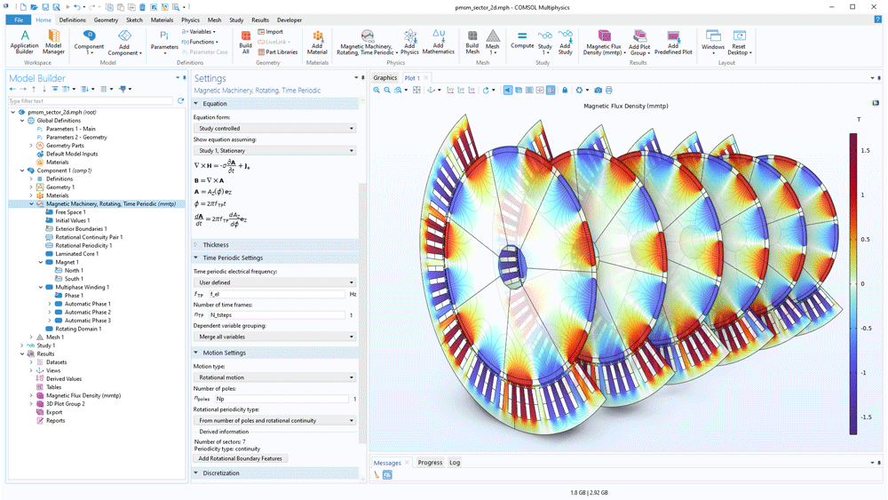
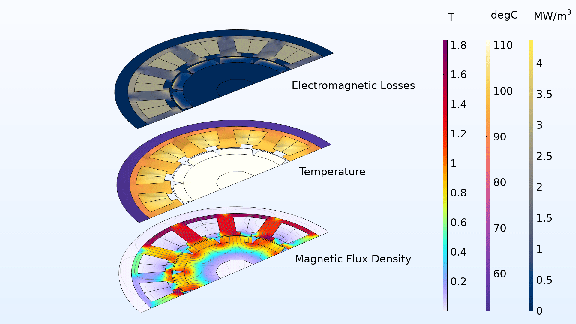
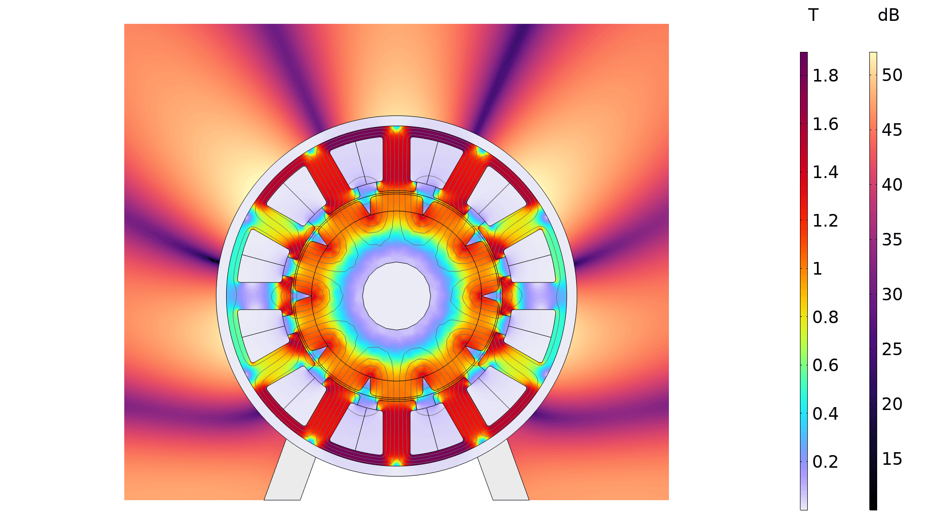
For nonlinear time-periodic problems, it is now possible to solve for the steady-state conditions directly using the new Magnetic Machinery, Rotating, Time Periodic interface. This is achieved by imposing periodicity in the time dimension and solving for all time frames at once with a stationary solver. The approach saves a considerable amount of computation time, since the alternative would be to run a time-dependent problem until the periodic steady state has been reached. Furthermore, this approach gives direct access to frequency-domain content (higher-order harmonics), for use in advanced multiphysics contexts. Typical use cases are motor and transformer studies, where the lamination loss and the electromagnetic forces are coupled with heat transfer, structural mechanics, and pressure acoustics — with a special focus on parametric sweeps and optimization studies. View this new interface in the Permanent Magnet Motor with Campbell Diagram and Permanent Magnet Motor Efficiency Map tutorial models.
Periodicity Support for the Single Conductor Coil and the Multiturn Coil
For coils and generic conductors (either stranded or solid), there is now true periodicity support in 3D. The Geometry Analysis subfeature used for the Coil domain in the Magnetic Fields interface, the Magnetic and Electric Fields interface, and the Rotating Machinery, Magnetic interface have now been equipped with a Periodic Boundaries subfeature that is used together with the Periodic Condition feature. This is particularly useful for electric machine models that have a form of sector symmetry, as showcased in the Motor Tutorial Series.
New Multiphysics Interfaces and Multiphysics Couplings for Motors and Generators
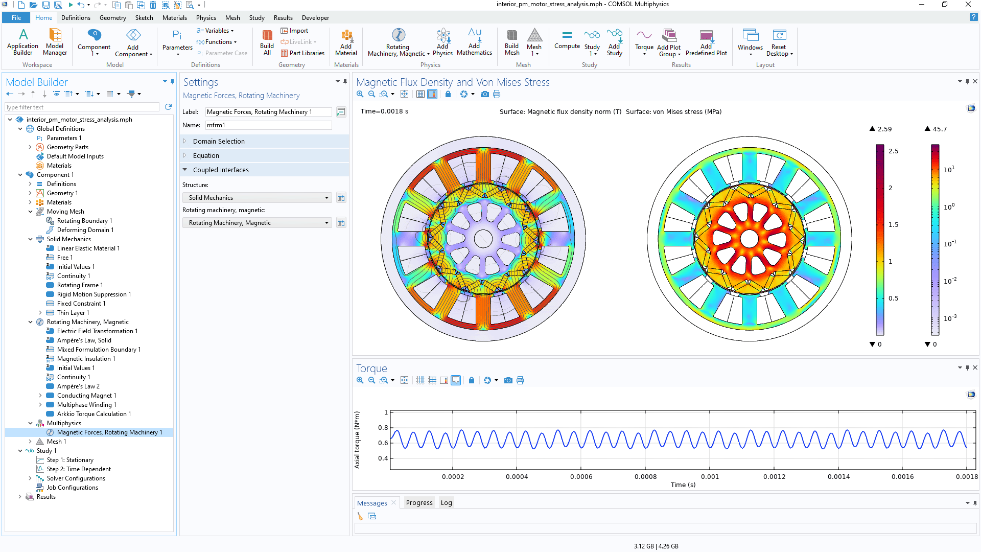
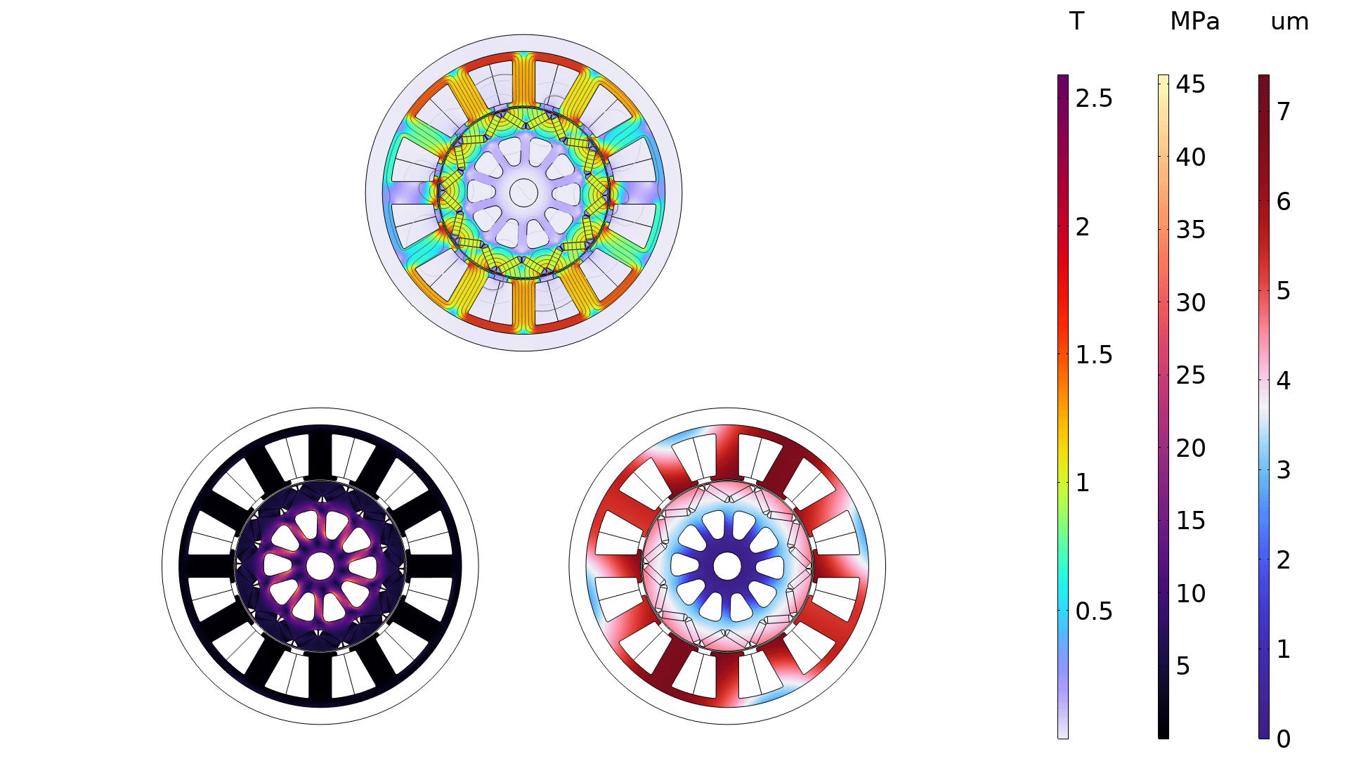
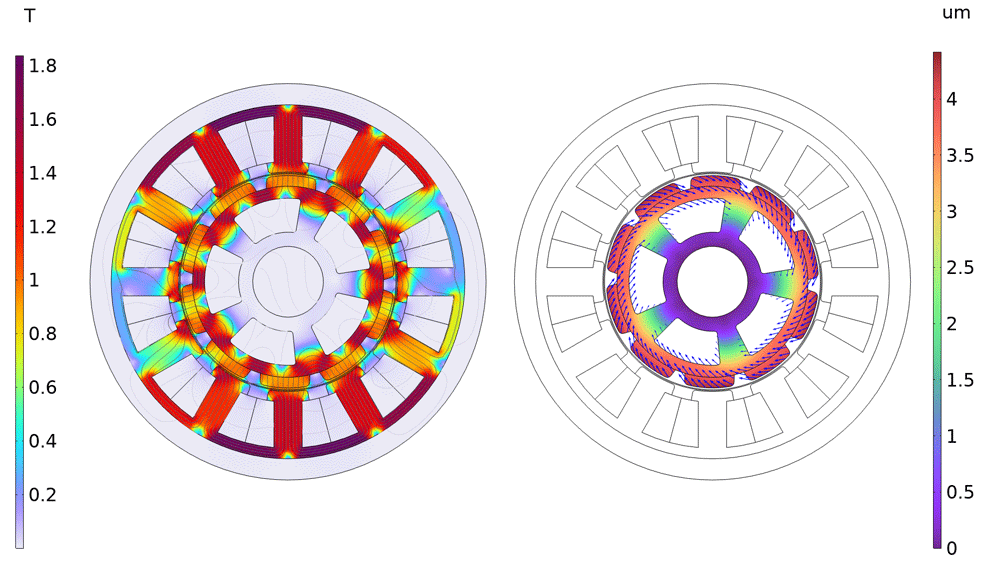
The new Magnetic–Elastic Interaction in Rotating Machinery multiphysics interface combines a Solid Mechanics interface with a Rotating Machinery, Magnetic interface, using the Magnetic Forces, Rotating Machinery multiphysics coupling. This multiphysics coupling connects the structural and electromagnetic physics at the domain level. It adds the loading caused by Maxwell stresses on a deformable and rotating structure. Note that this multiphysics interface requires the Structural Mechanics Module.
The Magnetic–Rigid Body Interaction in Rotating Machinery multiphysics interface combines a Multibody Dynamics interface with a Rotating Machinery, Magnetic interface through the same Magnetic Forces, Rotating Machinery multiphysics coupling. In this case, the multiphysics coupling computes how deformations and stresses originating from air gap forces are distributed in the stator and rotor. Some of the applications are magnetic bearings and motors with unbalanced rotors. Note that this multiphysics interface requires the Multibody Dynamics Module.
You can see these new additions in the Electromagnetic and Mechanical Analysis of an Interior Permanent Magnet Motor and Magnetic–Structure Interaction in a Permanent Magnet Motor tutorial models.
Restructured Magnetomechanics Multiphysics Couplings
The Magnetic Forces, Lorentz Coupling, and Magnetomechanical Forces multiphysics couplings have been deprecated and replaced by a single multiphysics coupling called Magnetomechanics. The coupling can be used to combine the Solid Mechanics interface with either the Magnetic Fields or Magnetic Fields, No Currents interface. If it is used to couple a Solid Mechanics interface with a Magnetic Fields, No Currents interface, the coupling becomes equivalent to the former Magnetic Forces coupling. If it is used to couple a Solid Mechanics interface with a Magnetic Fields interface, a check box enables the user to choose between options that are equivalent to the former Lorentz Coupling and Magnetomechanical Forces couplings. The new Magnetomechanics multiphysics coupling requires the MEMS Module, Structural Mechanics Module, or Acoustics Module.
Improved Handling of Solids and Liquids for the Magnetic Fields Interface
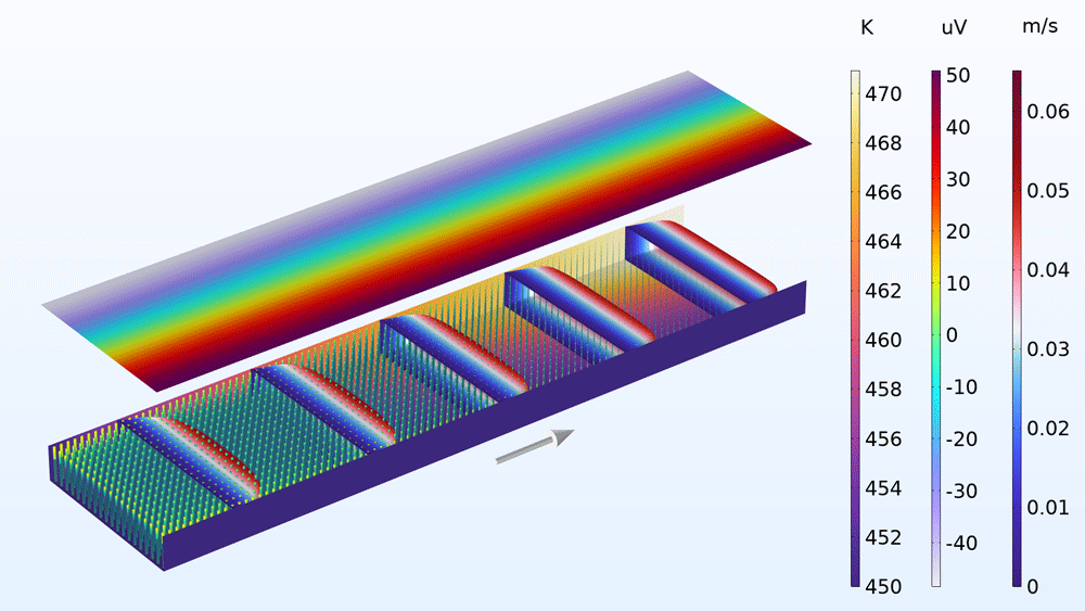
The new, ready-made Ampère's Law in Solids and Ampère's Law in Fluids features in the Magnetic Fields interface make it easier to build models with moving materials. These features provide a more user-friendly implementation that helps ensure that the appropriate coordinate frames of reference are used for liquids, gases, and vacuum on one hand and solid objects on the other. Furthermore, the features allow for a more intuitive setup of multiphysics couplings, with the Ampère’s Law in Fluids feature allowing for couplings with magnetohydrodynamics or plasma physics, for example, and the Ampère’s Law in Solids feature allowing for magnetomechanical couplings. View these new features in the Hartmann Boundary Layer and E-Core Transformer tutorial models.
Free Space Feature for the Magnetic Fields Interface
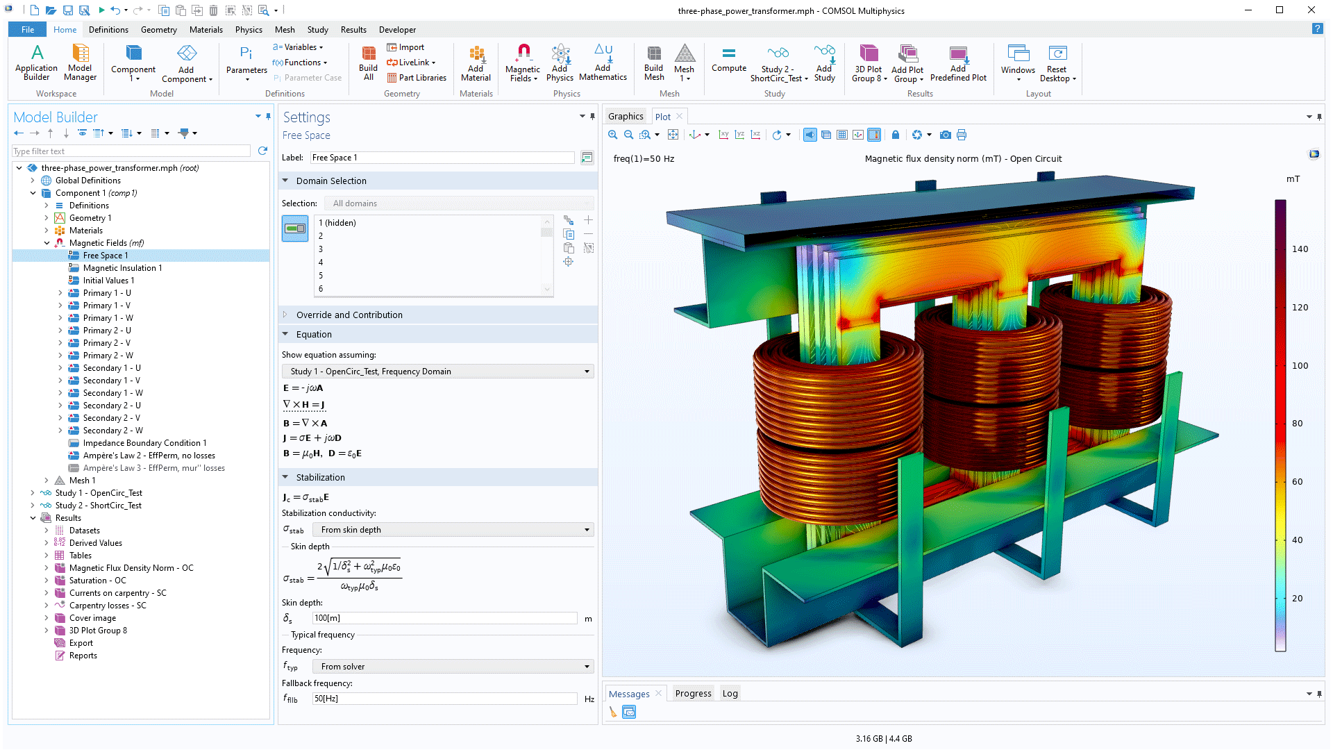
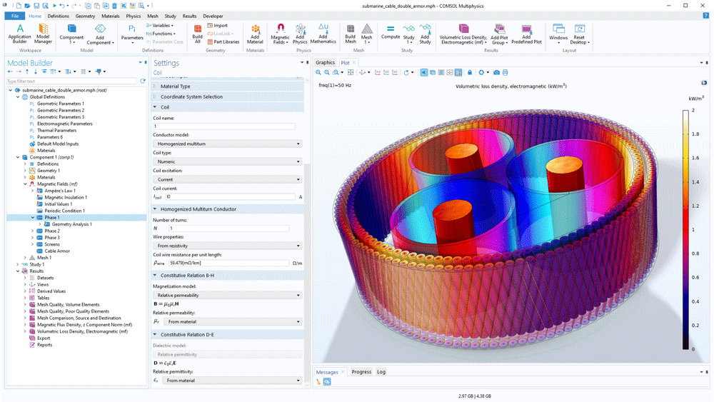
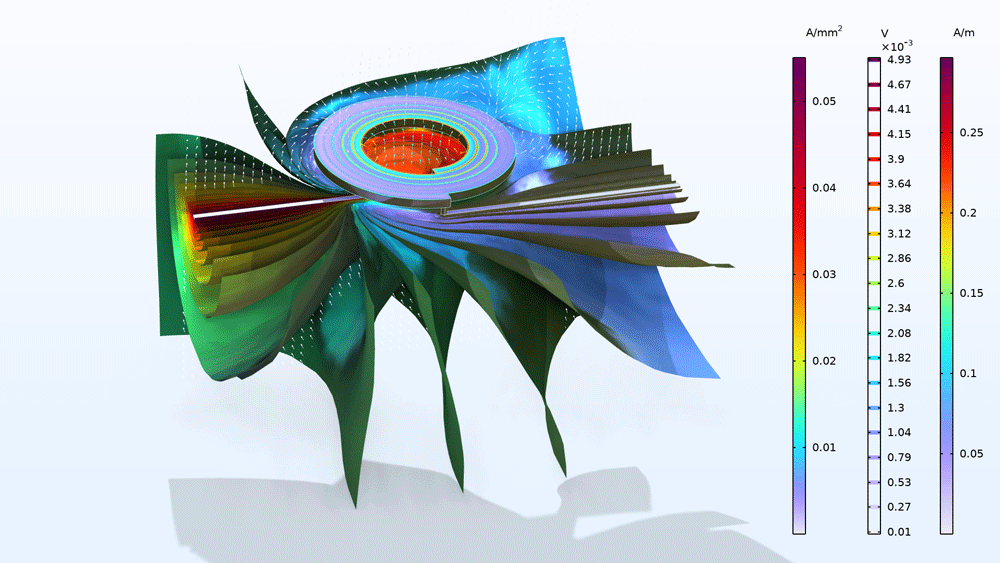
A new default feature, Free Space, is added to the Magnetic Fields interface. It is used to specify the physical conditions in close proximity to the modeled device — typically in air or vacuum. The feature provides a starting point to which other features (such as the Ampère’s Law in Solids or Fluids features) can be added to locally specify material properties and excitation forms. The Free Space feature comes with a built-in Stabilization option. This adds an artificial conductivity term such that the skin depth in free space is an order of magnitude larger than the modeled device at its typical operating frequency; a small conductivity that results in such a large skin depth is assumed to have little or no impact on the fidelity of the results, but its presence improves both the solver reliability and speed. A user-defined option is available, too, for manual tuning of the stabilization. The Submarine Cable 8 — Inductive Effects 3D and Multiturn Coil Above an Asymmetric Conductor Plate tutorial models showcase this new addition.
Litz Wire Support for the Multiturn Coil Domain
The Wire Properties section of the Homogenized Multiturn Conducutor coil has been extended to support several options typically used for litz wire modeling. This includes the option to specify the (AC) resistance per unit length — either taken from a user-defined analytic model, from measurements, or from a specification sheet provided by the supplier — and the option to specify the total effective resistance. These options enable an easier workflow when modeling stranded conductors that operate under nonideal conditions, such as Milliken conductors with interior contact resistance and litz wires (and coils) operating at higher frequencies.
Periodic Pair Feature Extended to 2D Axisymmetry
The Magnetic Fields interface now supports the Periodic Pair feature for the modeling of linear magnetic machinery in 2D axisymmetry (previously available in planar 2D only). This makes it possible to model rotationally symmetric (tubular) machinery in 2D. The periodic pair feature connects the physics on both sides of sliding meshes, where the periodicity is in the direction of motion. A typical use case for the periodic pair is the Linear Motor in 2D model.
Enhanced Support for Iterative Solvers and CAD Assemblies
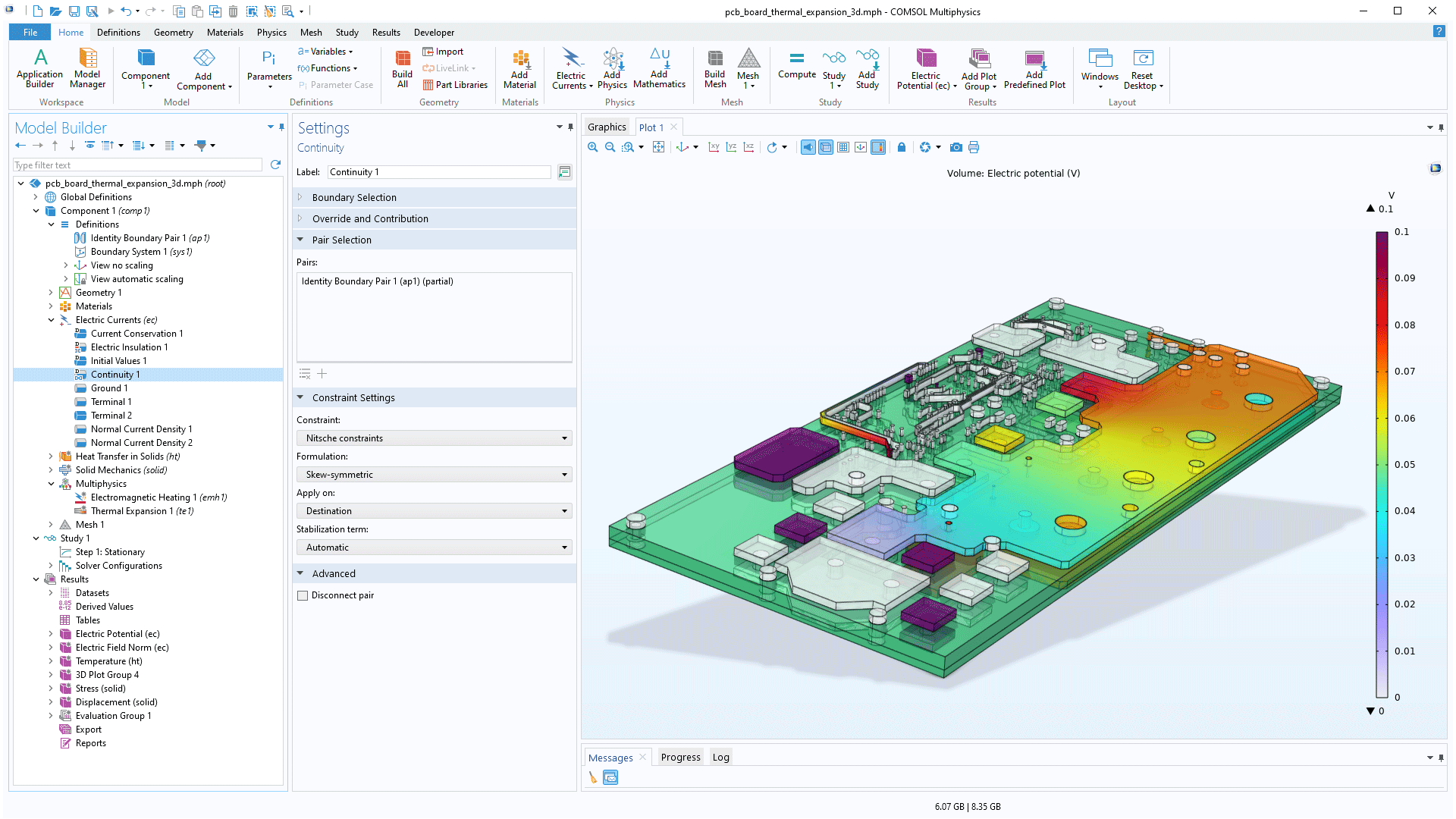
For the Continuity and Sector Symmetry pair features in the Electric Currents interface, the Magnetic Fields, No Currents interface, and the Rotating Machinery, Magnetic interface, a new constraint option is available for the scalar potential degree of freedom named Nitsche constraints. These constraints do not require conforming meshes and do not need a Lagrange multiplier either, simplifying the meshing sequence and allowing for a larger range of solver options.
Voltage Excitation for the Terminated Terminal
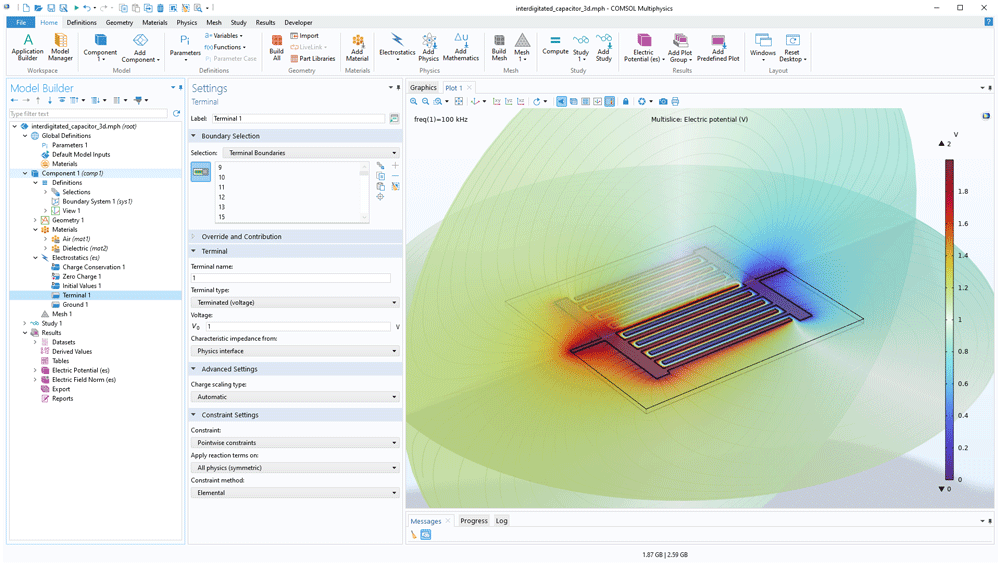
The Terminal feature in the Electrostatics interface, the Electric Currents interface, and the Magnetic and Electric Fields interface is equipped with a Terminated option. This enables you to connect the terminal to an impedance that might represent a load or a transmission line. The Terminated option has now been extended to support voltage excitation. This is suitable for modeling various high-frequency piezoelectric MEMS devices.
Debye Dispersion Model for Electric Currents
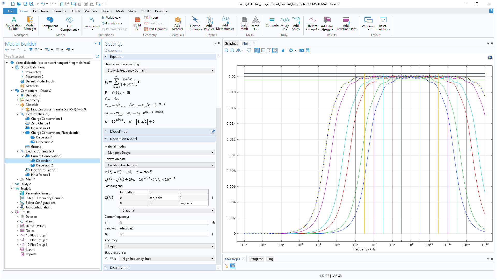
In the Electric Currents interface, dispersive polarization models have been introduced. These models describe transient effects in weakly conducting dielectrics. Under Current Conservation, when the material type is set to Solid, it is now possible to use the Dispersion dielectric material model. In the Dispersion subnode, the Debye or Multipole Debye dispersion models are available options. These models can be used in models of electromagnetic (EM) heating for bioelectromagnetics and tissue modeling, for example, and are available for frequency-domain and time-dependent analysis.
Piezoelectric Material, Layered Feature in Shell Interface
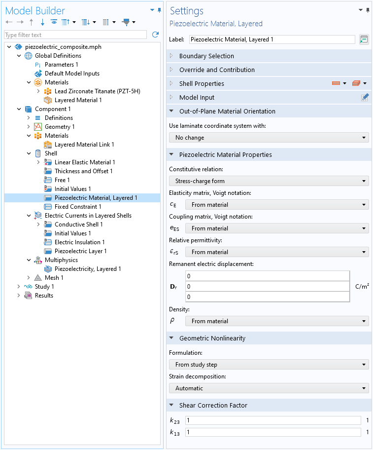
Similar to the Piezoelectric Material feature available in the Layered Shell interface in previous versions, a Piezoelectric Material, Layered feature has been added to the Shell interface. This addition saves assembly and computation time when solving thin piezoelectric composites with the Shell interface. Note that this feature requires the Structural Mechanics Module.
Floating Potential for the Conducting Shell and the Piezoresistive Shell
For the Electric Currents in Shells interface and the Electric Currents in Layered Shells interface, a new Floating Potential subfeature has been added to the Conductive Shell and Piezoresistive Shell features. The Floating Potential node is used when modeling a metallic electrode at floating potential. Note that the Piezoresistive Shell feature requires the MEMS Module.
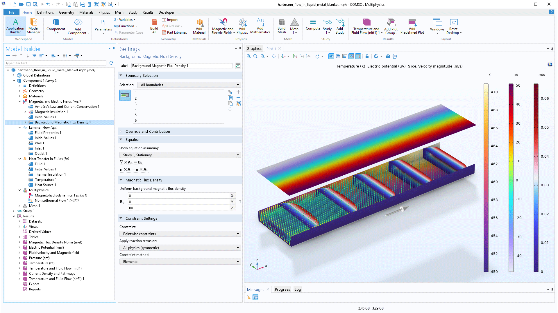
Background Field Feature for the Magnetic and Electric Fields Interface
A new feature, Background Magnetic Flux Density, has been added to the Magnetic and Electric Fields interface. This provides a convenient way to add a background field when modeling liquid metals, for example. You can see this new feature in the Hartmann Flow in Liquid Metal Blanket with Heat Transfer tutorial model.
New and Updated Tutorial Models and Geometry Parts
COMSOL Multiphysics® version 6.2 brings several new and updated tutorial models and geometry parts to the AC/DC Module.
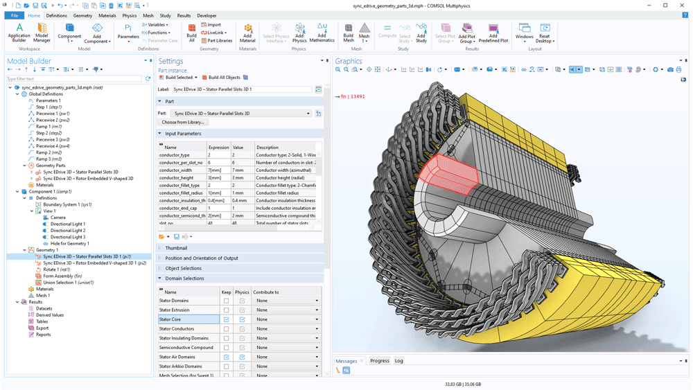
Motor Tutorial Series
Motor Tutorial Series, Geometry Parts
Permanent Magnet Motor Efficiency Map
Application Library Title:
pm_motor_2d_efficiency_map
Download from the Application Gallery
Permanent Magnet Motor with Campbell Diagram
Application Library Title:
pm_motor_2d_campbell_diagram
Download from the Application Gallery
Electromagnetic and Mechanical Analysis of an Interior Permanent Magnet Motor
Application Library Title:
interior_pm_motor_stress_analysis
Download from the Application Gallery
Magnetic–Structure Interaction in a Permanent Magnet Motor
Application Library Title:
pm_motor_2d_structure_interaction
Download from the Application Gallery
Resonant Spiral Coil
Application Library Titles:
resonant_spiral_coil_3d
resonant_spiral_coil_2daxi
Download from the Application Gallery
Hartmann Flow in Liquid Metal Blanket with Heat Transfer
Application Library Title:
3d_hartmann_flow_with_heat_transfer
Download from the Application Gallery
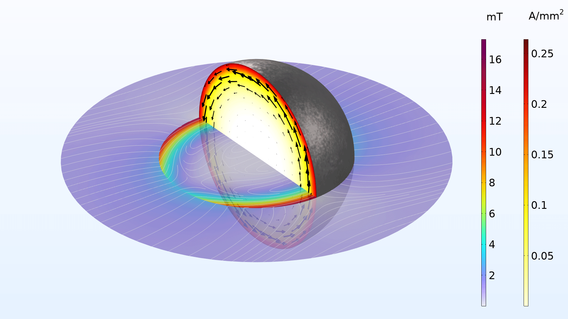
Iron Sphere in a Magnetic Field
Application Library Titles:
iron_sphere_bfield_00_introduction
iron_sphere_bfield_01_static
iron_sphere_bfield_02_60hz
iron_sphere_bfield_03_20khz
iron_sphere_bfield_04_13mhz
Download from the Application Gallery
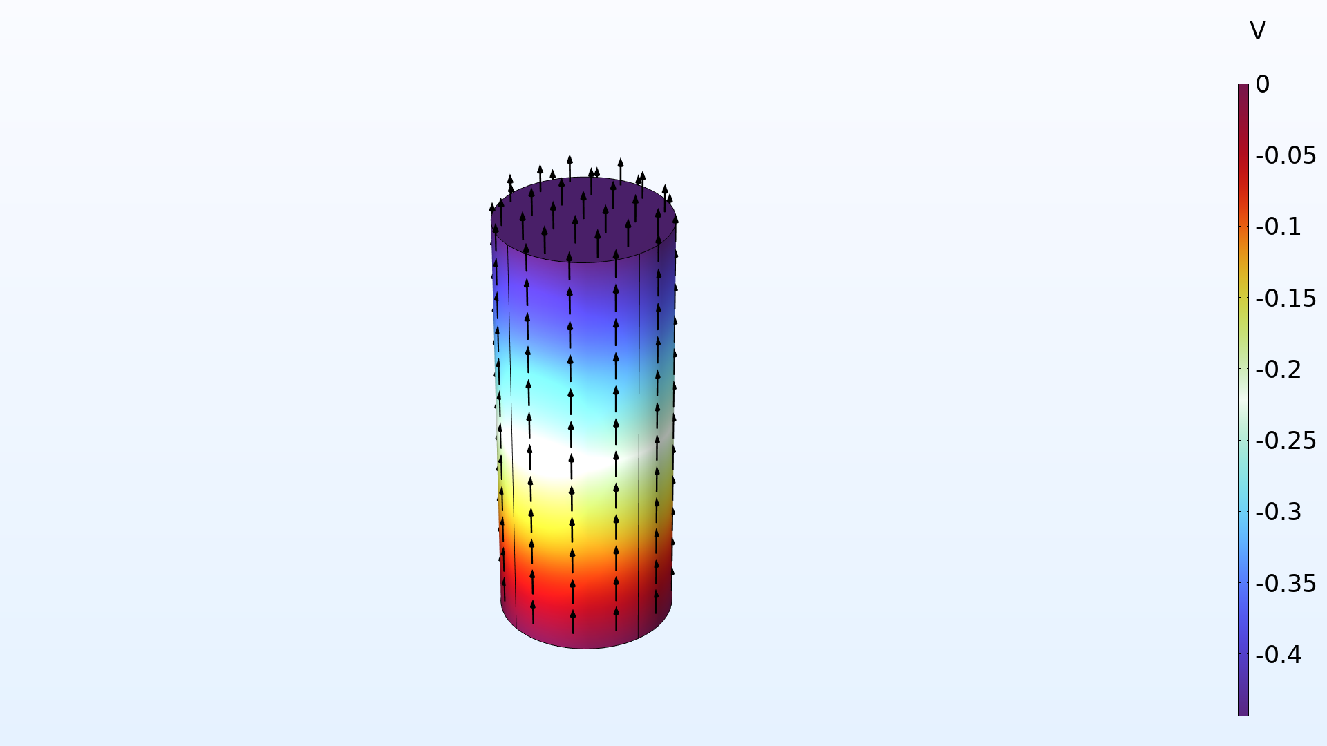
FEM Resistor in Circuit
Application Library Title:
circuit_fem_resistor
Download from the Application Gallery