support@comsol.com
Mesh Updates
COMSOL Multiphysics® version 6.2 introduces the ability to use swept meshing for more complex geometries, a new feature for automatically generating identical mesh for faces and edges, and various remeshing operations for imported meshes. Learn more about these updates below.
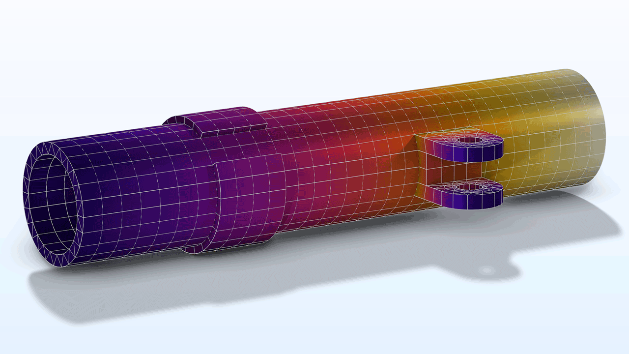
Swept Meshing Improvements
In this version, more types of geometries can be automatically meshed using the Swept operation. For example, the boundaries along the sweep can now have a rectangular imprint with edges tangent or perpendicular to the local sweep direction. Previously, a swept mesh could be created after a manual partition of such faces.
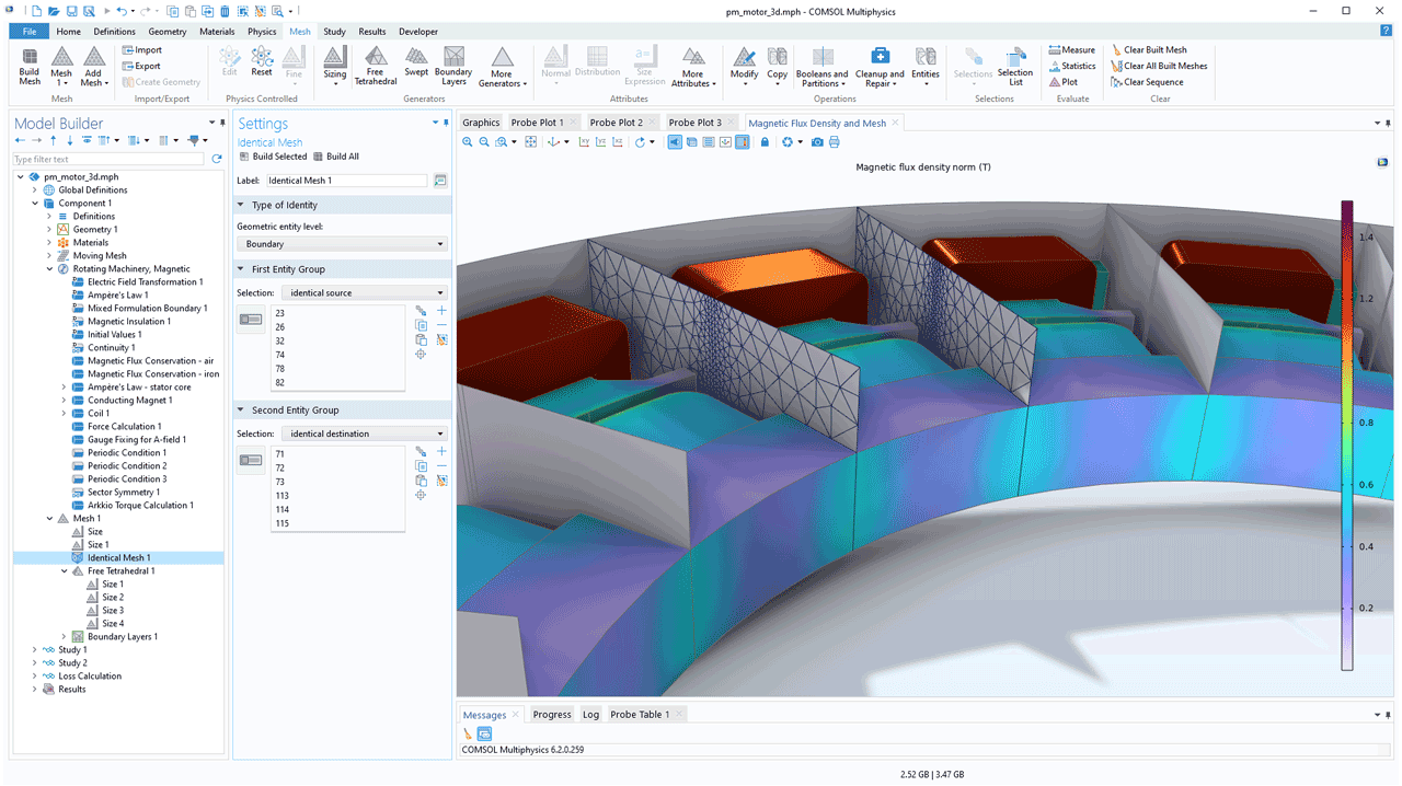
Easier to Generate Identical Meshes on Periodic Boundaries
A new Identical Mesh attribute can be used to specify pairs of entity groups for which an identical mesh is needed, such as for periodic boundaries. You can simply add this attribute to the meshing sequence and then continue to mesh the domains. The mesh generators will automatically account for the element sizes and narrow domain regions while ensuring an identical mesh. For physics-controlled meshing sequences, Identical Mesh attributes can be included when needed. In this version, manually setting up such a meshing sequence is much faster; previous versions required generating a mesh for one side of the pair and then using a copy operation to obtain an identical mesh on the other side before generating the mesh in the domains.
View the Identical Mesh attribute in the following tutorial models:
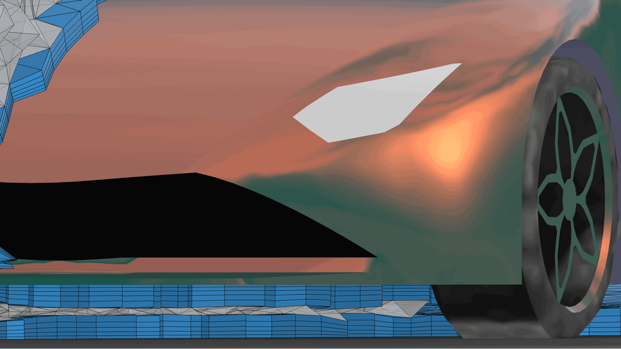
New Remeshing Operations for Imported Meshes
A new set of remeshing operations has been included that makes it easier to generate a mesh for simulation from an imported mesh or from topology optimization results. The Remesh Faces (available for 3D), Remesh Edges, and Remesh Domains (available for 2D) operations support the element-sizing attributes and the new Identical Mesh attribute. In addition, a new Fixed Mesh attribute is available for the remeshing operations to keep the existing mesh fixed on selected boundaries and edges. The STL Import Tutorial Series showcases these new operations.
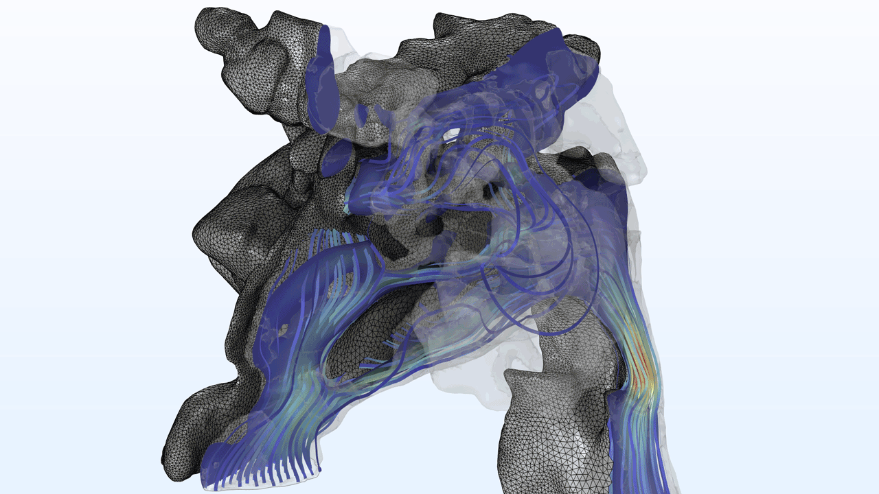
Boundary Layer Meshing Improvements
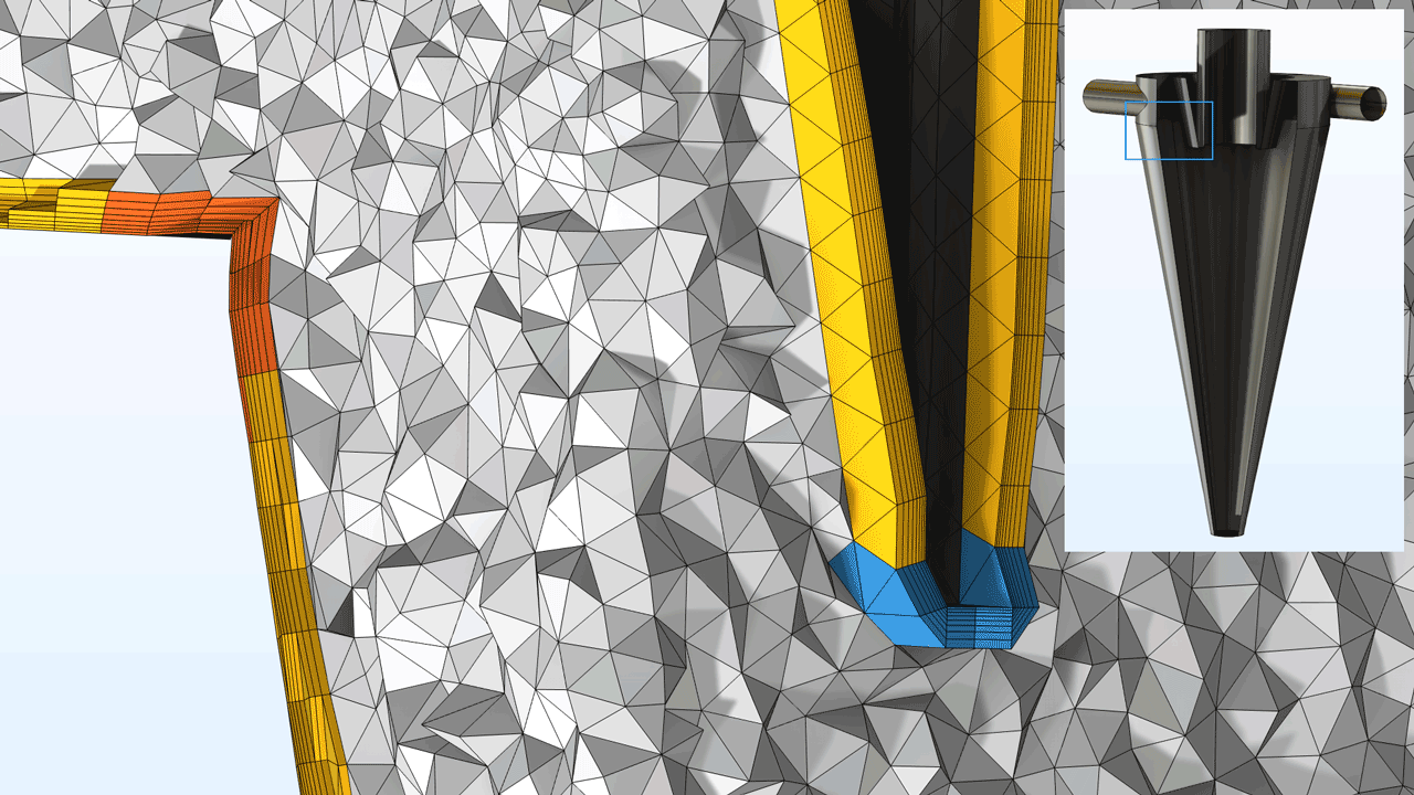
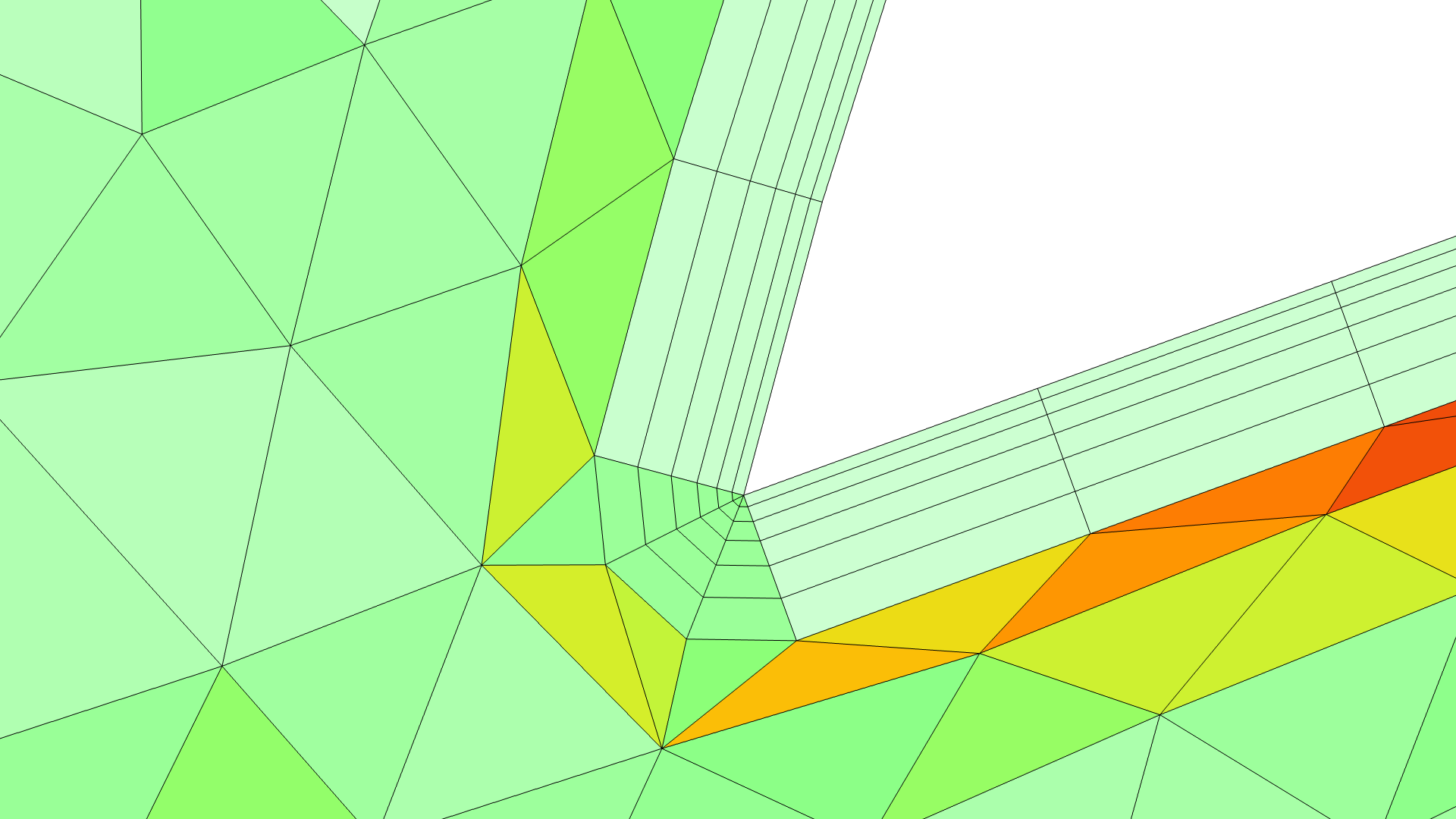
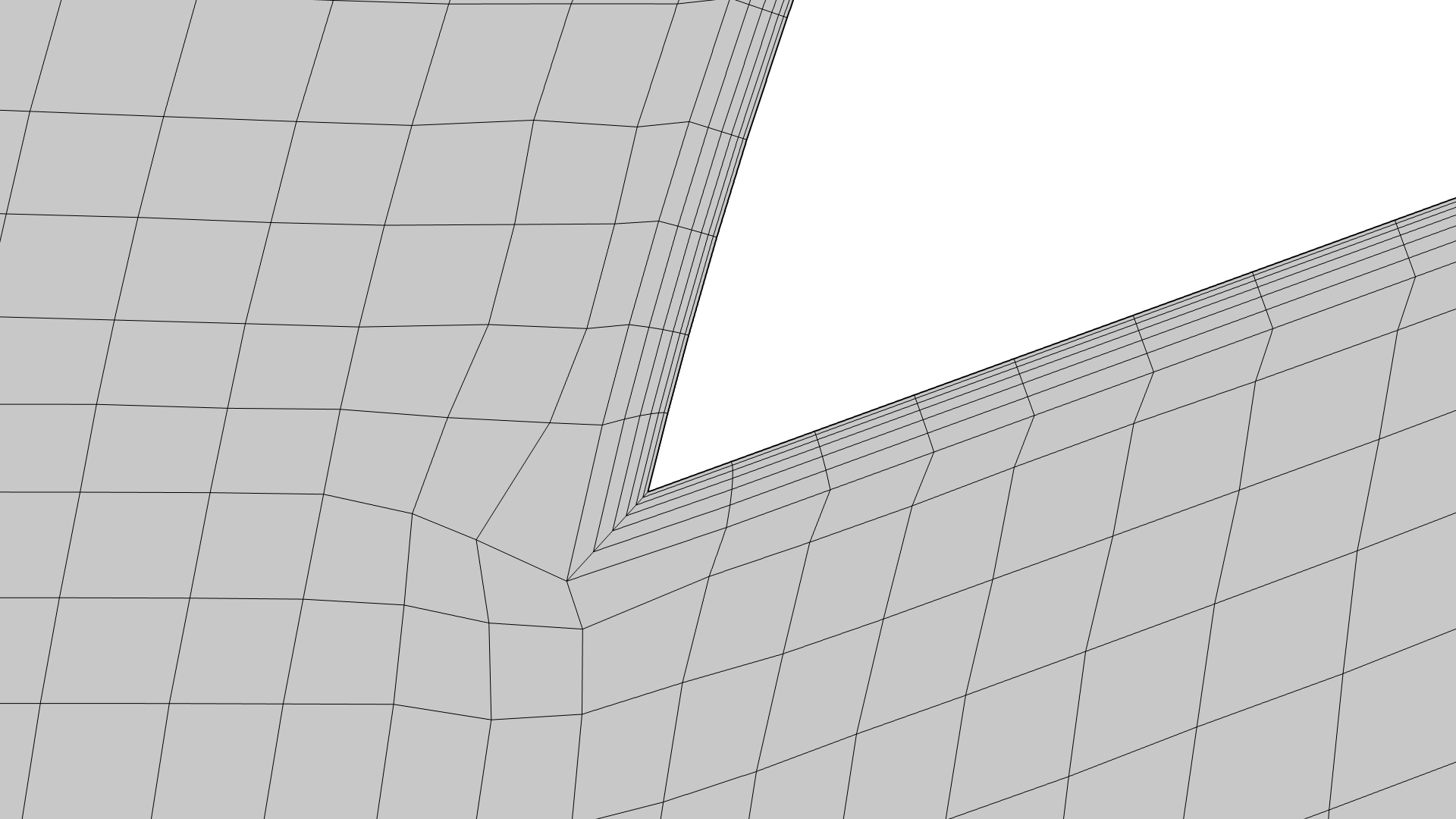
The Boundary Layers operation has been improved and now allows for the generation of thicker high-quality boundary layer meshes for even more complex cases.
A new Corner Properties attribute is available for easier manual control of boundary layer generation in corners. This attribute provides a way to override the overall settings for a selection of corners when another approach is more appropriate. You can see this new feature in the Boundary Layer Meshing Tutorial Series.
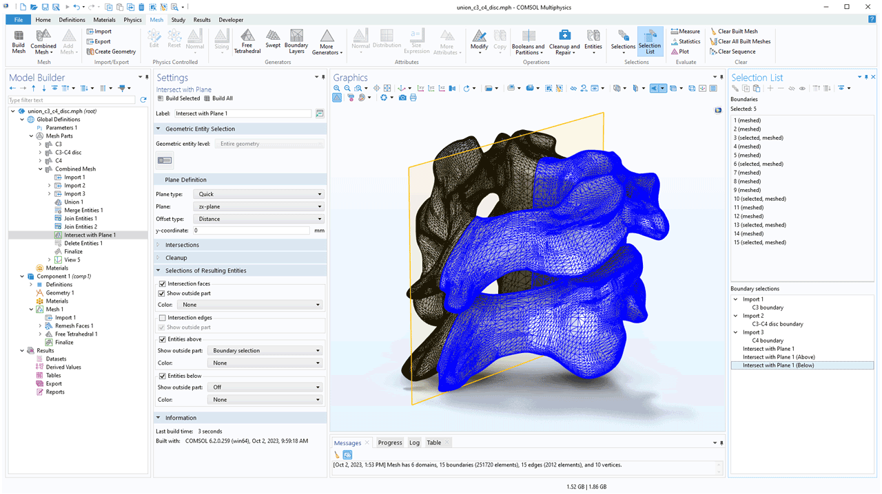
Creating Named Selections in Imported Meshes
It is now possible to set up named selections of entities for imported meshes using the Explicit Selection and Adjacent Selection nodes or by using certain mesh operations to define selections on the resulting mesh. The selections can be colored and used in subsequent meshing operations and other model definitions. The ability to name selections simplifies setting up the physics and is especially useful when parameterizing models and creating simulation apps. The Mesh ribbon tab contains a Selection List button that opens up the Selection List window, where all named selections in the model can be viewed. You can see this new functionality in the STL Import Tutorial Series.
New Tutorial Models
COMSOL Multiphysics® version 6.2 includes two new meshing tutorial models.
Boundary Layer Meshing — Exploring the Settings
Application Library Title:
valve_boundary_layers
Download from the Application Gallery
Boundary Layer Meshing — Adding Boundary Layers to an Imported Mesh
Application Library Title:
valve_boundary_layers_import
Download from the Application Gallery