Composite Materials Module
COMSOL Multiphysics® version 5.4 introduces the new Composite Materials Module. This add-on to the Structural Mechanics Module allows you to model laminates and layered materials, with new Layered Material technology.
Composite Materials Module Overview
There are two different formulations for layered shells: one that is based on a classical laminate theory and another that is based on a more complete 3D theory. The former is implemented in a material model in the existing Shell interface, whereas the latter forms the basis for the new Layered Shell interface. The user interface includes tools for specifying isotropic and anisotropic material properties in layered materials together with dedicated visualization tools used to display the layers graphically.
This module is useful for structural analysis of composite laminates, and can be coupled to the Heat Transfer Module and the AC/DC Module for multiphysics analysis of composite materials. By combining the Composite Materials Module with the Heat Transfer Module, you get more sophisticated heat transfer and thermal expansion functionality. Similarly, you can combine the Composite Materials Module with the AC/DC Module for layered materials functionality within the Electrostatics and Electric Currents interfaces.
Defining Laminates
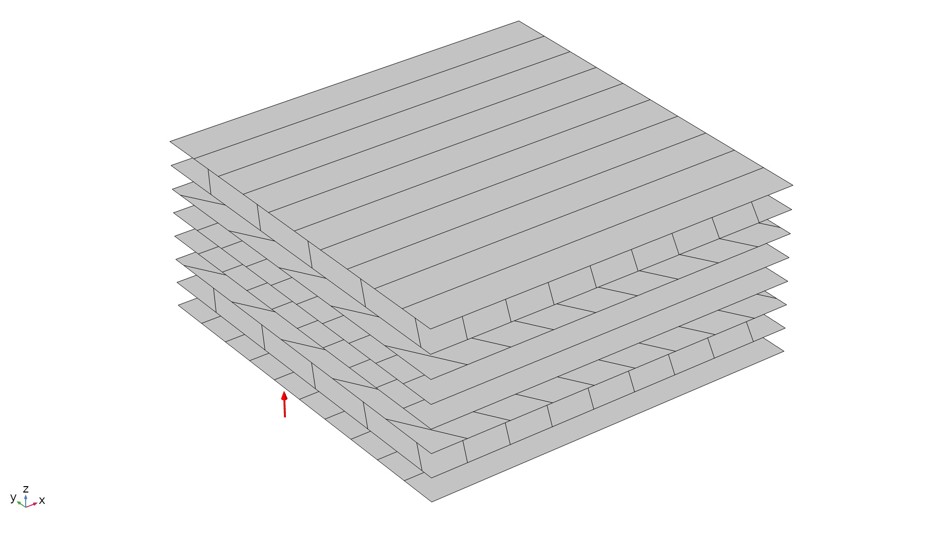
Using the new Layered Material node, it is possible to define a layup where each layer has its own material data, thickness, and principal orientation. Layered materials defined in this way can be combined to create new layered materials. This is particularly convenient when the layup is repetitive or when modeling ply drop-off. It is also possible to define material properties for the interfaces between layers. Preview plots in 3D and 2D are available for visualizing the input data.
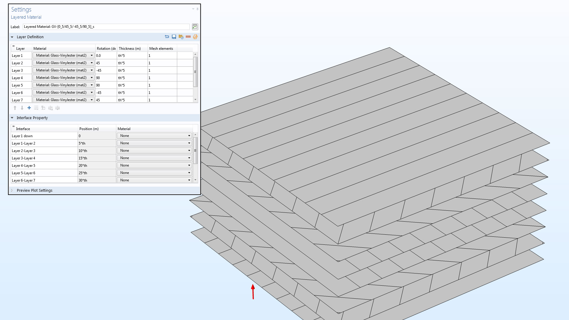 Defining the layup of a layered material (inset) and a preview plot showing principal orientations of each layer.
The Layered Shell Interface
The Layered Shell interface is used for detailed analysis of a laminate, with results including full 3D stress and strain distribution. You can, for example, compute interlaminar stresses and study stress variations inside each lamina. Boundary conditions can be placed on individual layers, and even on individual interfaces between layers. The materials in the individual layers can be nonlinear. The formulation of this physics interface makes it suitable for thick and moderately thin shells with a limited number of layers. Each layer can have a different number of elements through the thickness.
Models that use the Layered Shell interface:
- Micromechanics and Stress Analysis of a Composite Cylinder
- Forced Vibration Analysis of a Composite Laminate
- Bending of a Simply Supported Composite Laminate
- Thermal Expansion of a Laminated Composite Shell
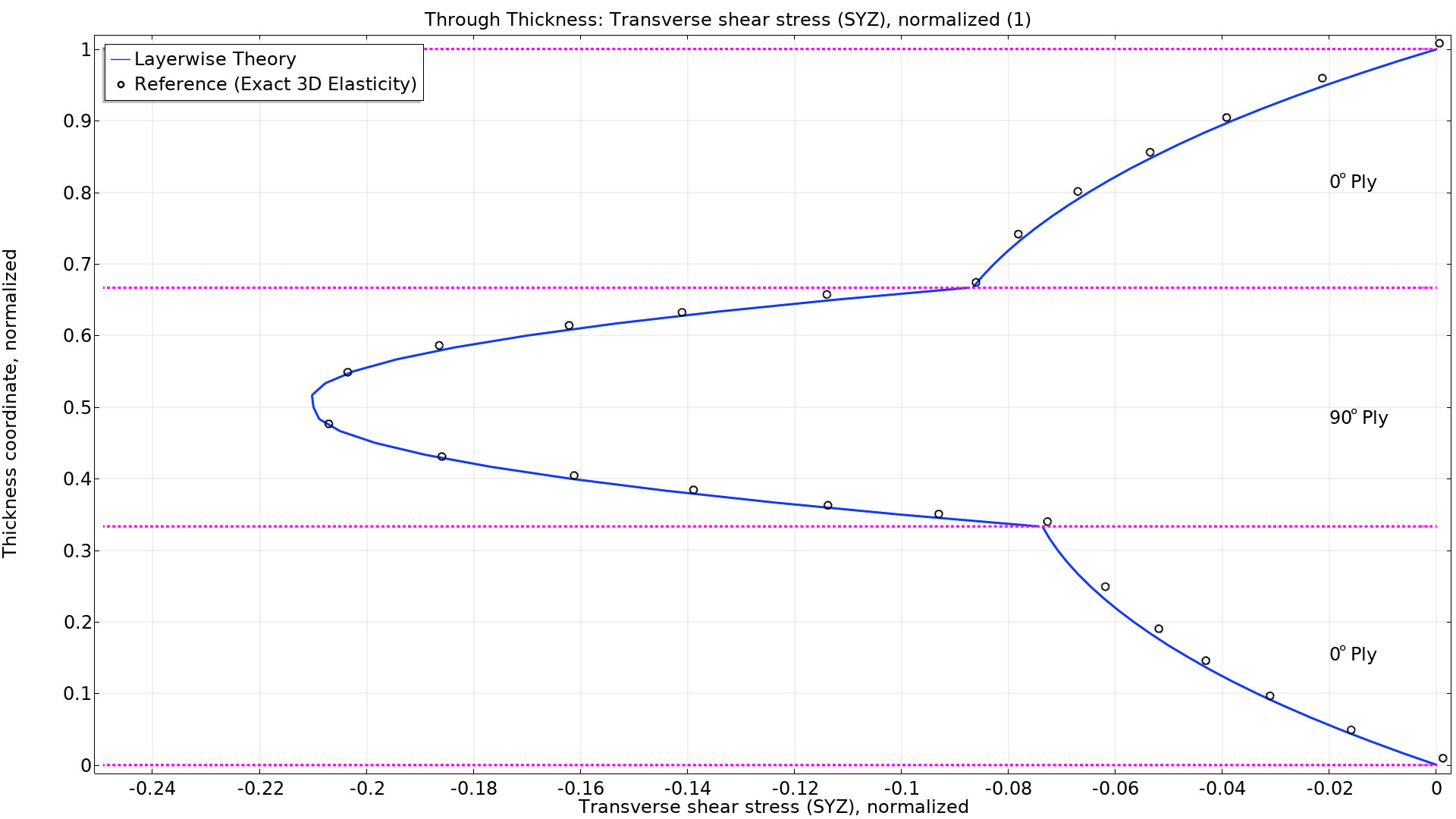
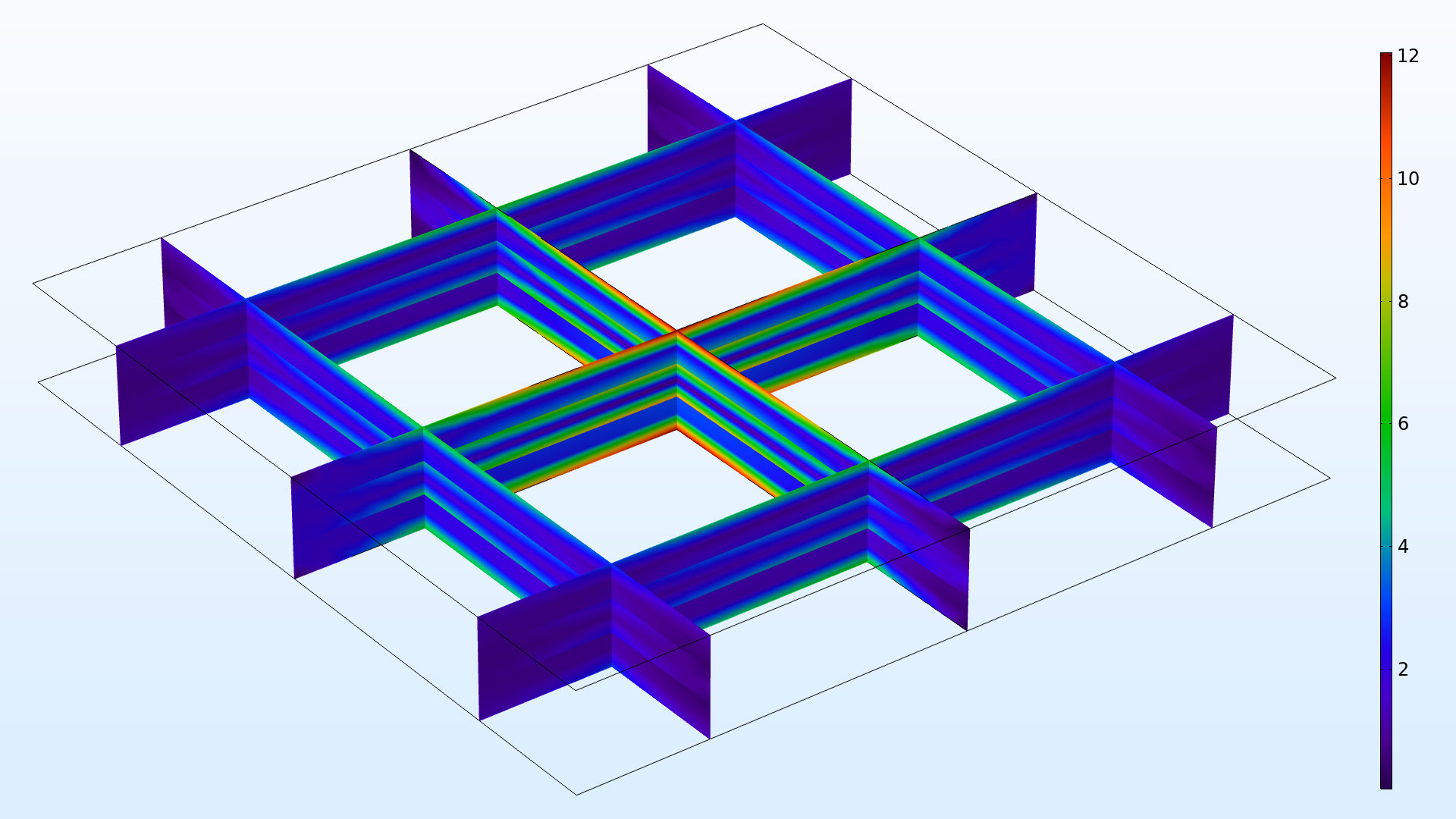
Transverse shear stresses in a three-layer laminate; comparison between the Layered Shell interface and exact 3D solution.
The Layered Linear Elastic Material
With the Composite Materials Module, the previously available Shell interface is augmented with a new material model: Layered Linear Elastic Material. This material model, which is suitable for thin and moderately thick shells, can accommodate many layers without significant performance impact. It is based on an equivalent single layer approach, where all layers are aggregated into an equivalent material.
Models that use the Layered Linear Elastic Material feature:
- Buckling of a Composite Cylinder
- Micromechanics and Stress Analysis of a Composite Cylinder
- Failure Prediction in a Laminated Composite Shell
- Material Characteristics of Laminated Shell
- Bending of a Simply Supported Composite Laminate
- Stress and Modal Analysis of a Wind Turbine Composite Blade
 The third eigenmode of a wind turbine blade designed as a sandwich structure.
Specialized Tools for Result Evaluation
When evaluating results in layered structures, some extra tools are needed. A special Layered Material dataset makes it possible to display results from layered shells using a full 3D solid representation. It is also possible to create slice plots of several types. For graphing, there are special tools for visualizing the variation in the through thickness direction.
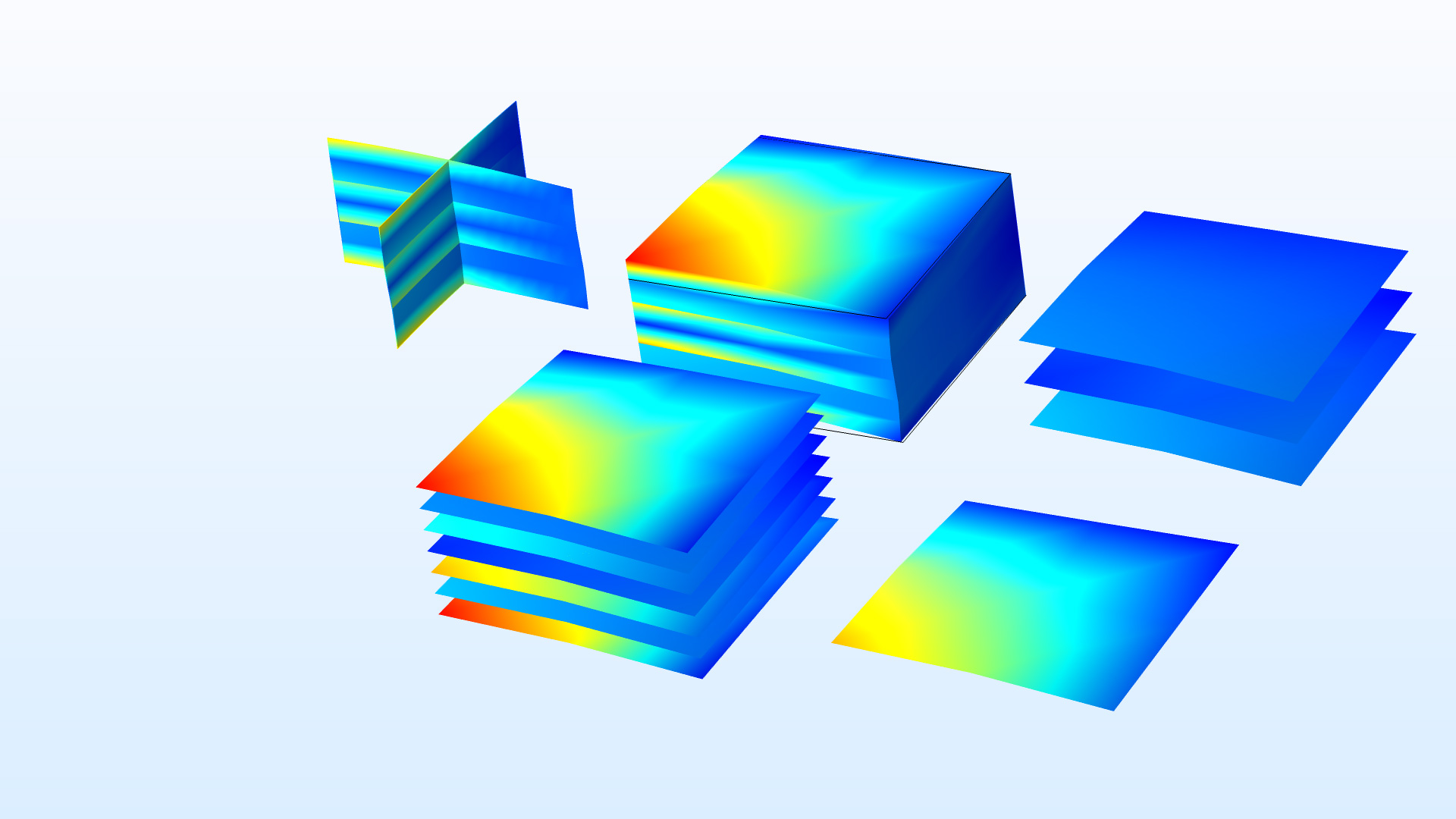 Different types of visualization of a thick three-layer laminate.
Multiphysics in Layered Structures
All physics interfaces for layered materials share the same representation of the layup of a laminate. This means that it is easy to set up models describing multiphysics within the layers of the structure. For the common case of thermal expansion, a predefined multiphysics coupling between the Heat Transfer in Shells interface and the Layered Shell interface is available. Other multiphysics options include the thermoelectric effect, when combined with the Heat Transfer Module, and Joule heating, when combined with both the Heat Transfer Module and the AC/DC Module.
Fluid-structure interactions involving composite materials can be modeled by combining the Shell interface for layered linear elastic materials with one of the many interfaces for fluid flow. By combining the Composite Materials Module with the Acoustics Module, a dedicated multiphysics coupling enables acoustic-structure interaction with layered linear elastic materials.
You can see the implementation of multiphysics, with thermal expansion, in the Thermal Expansion of a Laminated Composite Shell model.
New Tutorial Models
COMSOL Multiphysics® version 5.4 includes several new tutorial models.
Material Characteristics of a Laminated Shell
 Orientations in a [0/60/-60/0/0/-60/60/0] laminate. In this example, the equivalent elastic properties for a homogeneous shell are computed and compared with reference values.
Search in the Application Library:
laminated_shell_material_characteristics
Bending of a Simply Supported Composite Laminate
Stress in a simply supported three-layer plate subjected to bending.
Search in the Application Library:
simply_supported_composite_laminate
Buckling of a Composite Cylinder
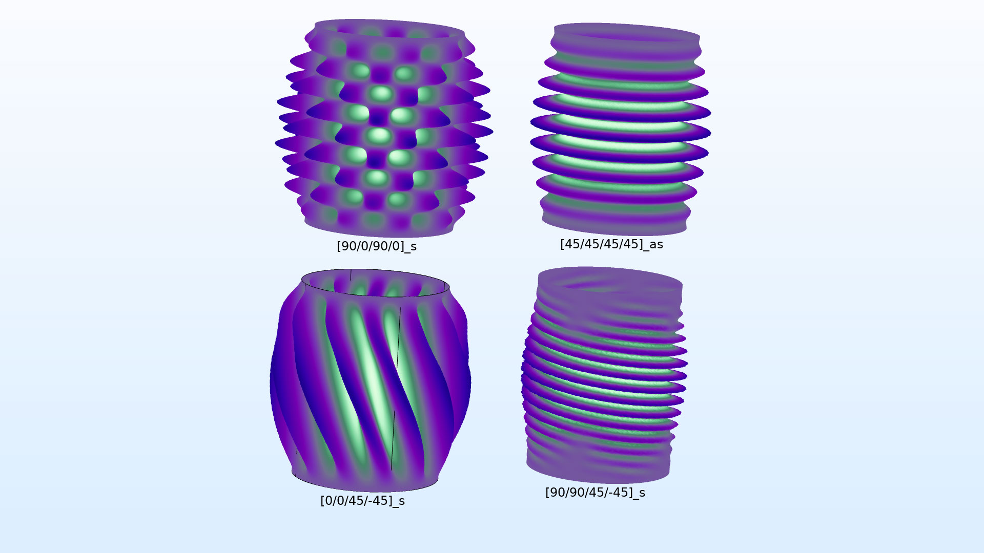
Buckling modes for the same shell with different choice of fiber orientations in the lamina.
Search in the Application Library:
composite_cylinder_buckling
Forced Vibration Analysis of a Composite Laminate
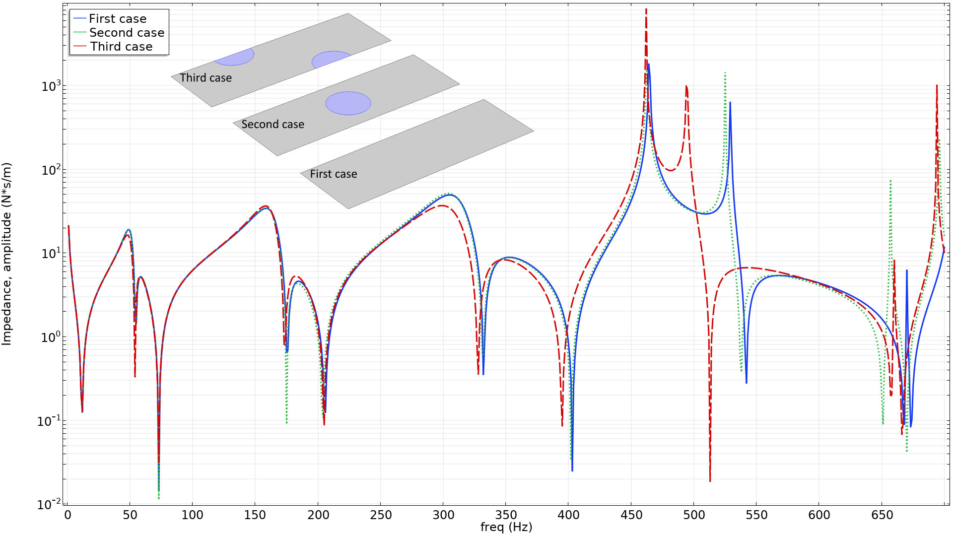 Impedance of a layered plate with and without debonded regions.
Search in the Application Library:
forced_vibration_of_a_composite_laminate
Stress and Modal Analysis of a Wind Turbine Composite Blade
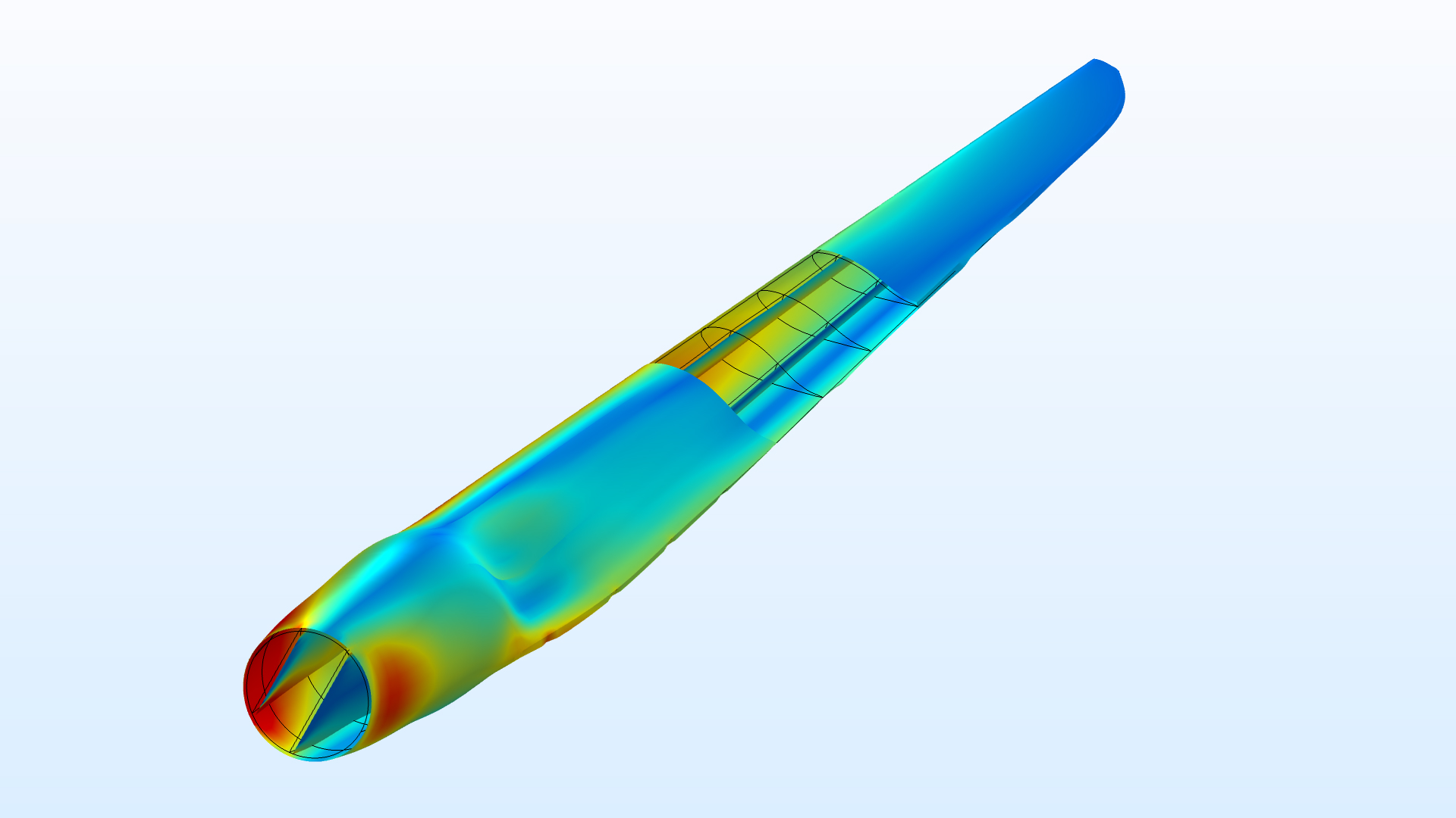 Stresses in a wind turbine blade. The skin has 19 layers and the core is a thick PVC foam surrounded by several layers of glass fiber composite on each side combined with an external carbon fiber cladding.
Search in the Application Library:
wind_turbine_composite_blade
Thermal Expansion of a Laminated Composite Shell
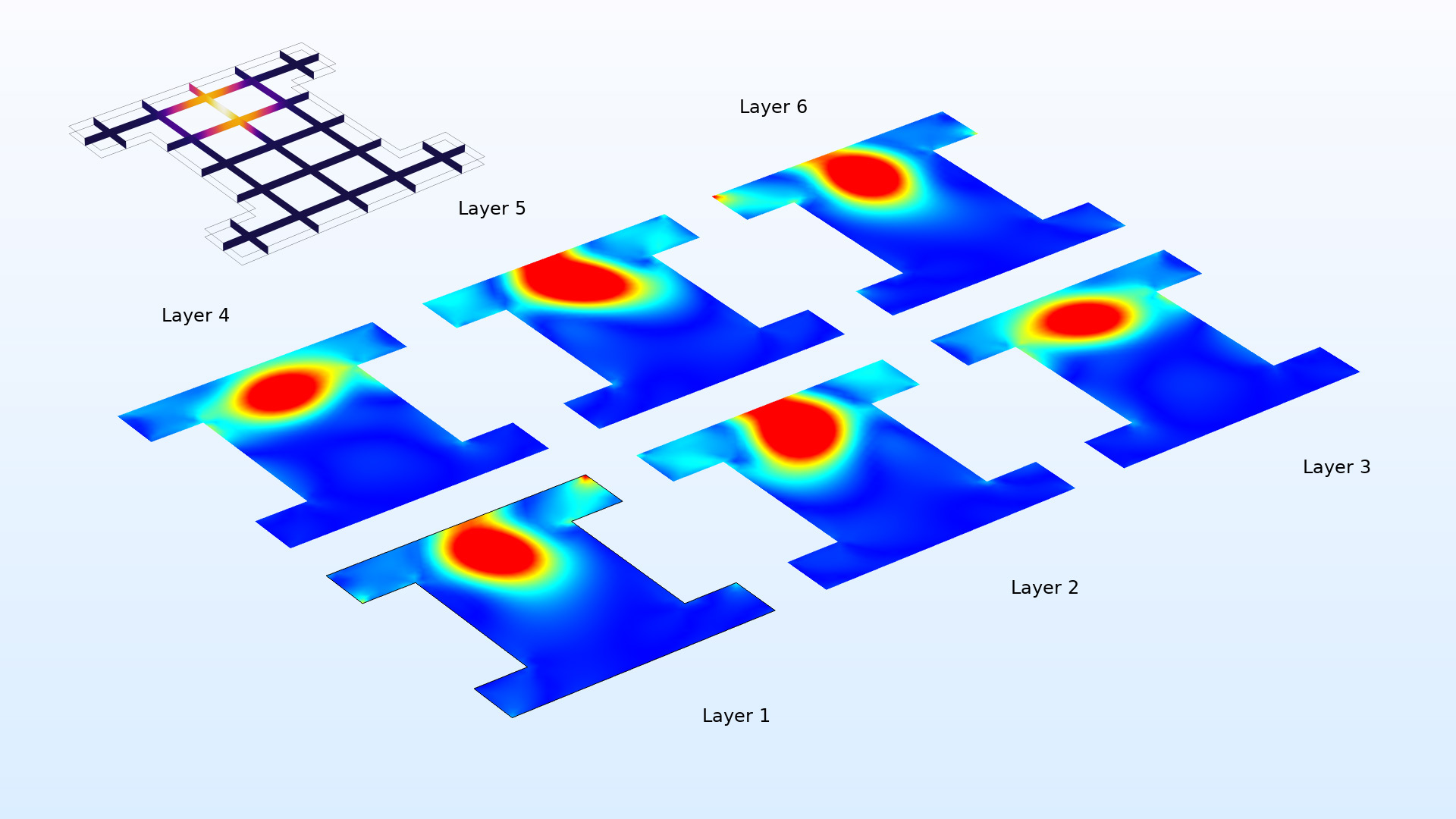 Effective stress caused by heating in a six-layer composite.
Search in the Application Library:
thermal_expansion_of_a_laminated_composite_shell
Failure Prediction in a Laminated Composite Shell
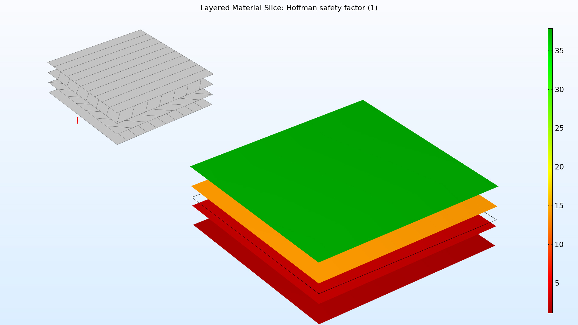 Safety factors according to the Hoffman criterion for a uniaxially loaded laminate. The principal orientations of the lamina are shown in the inset.
Search in the Application Library:
failure_prediction_in_a_laminated_composite_shell
Micromechanics and Stress Analysis of a Composite Cylinder
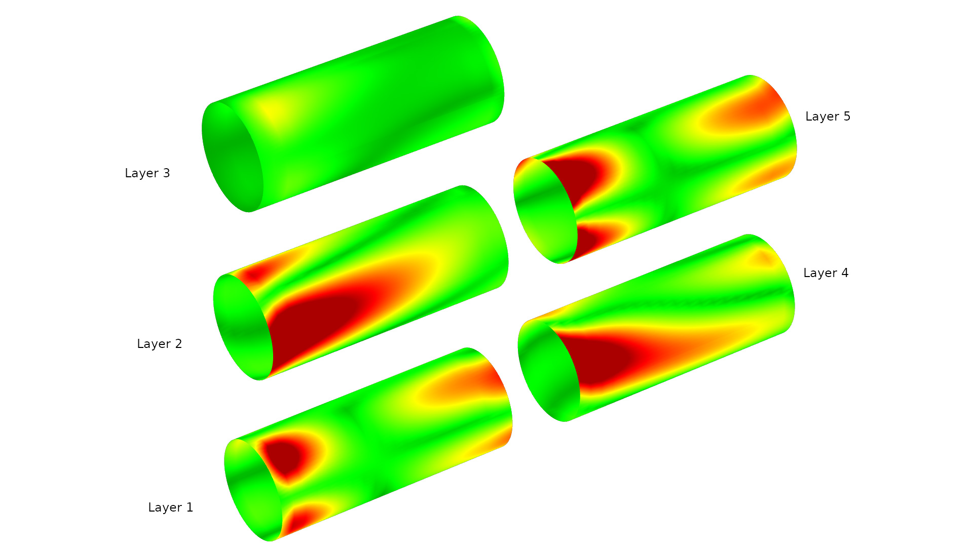 Stresses in all layers of a tube designed as a five-layer composite laminate.
Search in the Application Library:
composite_cylinder_micromechanics_and_stress_analysis