

We like to feature a certain waveguide model in our RF and microwave heating webinars because it illustrates the concept in a way that is easy to understand. Here it is again, serving as a quick intro to modeling RF and microwave heating.
Brief Intro to RF and Microwave Heating
When energy from electromagnetic fields is transformed into thermal energy, RF heating occurs. There are two different types of RF heating methods: induction and dielectric. Induction heating takes place in materials with a high electrical conductivity, such as copper or other metals, for instance. Eddy currents are induced by the alternating electromagnetic field and the resistive losses heat up the material. Dielectric heating, on the other hand, happens in — you guessed it — nonconducting material, when it’s subjected to a high-frequency electromagnetic field. The alternating electromagnetic field causes the dielectric molecules to flip back and forth and the material to heat up due to internal friction.
The example we will go through here involves both induction and dielectric heating.
A Waveguide Bend with Microwave Heating
To redirect microwaves passing through a waveguide, you can add a bent section. This is appropriately referred to as a waveguide bend. When you have such a bend in between two straight, rectangular waveguides, it will look something like this:
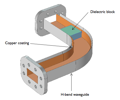
Schematic of an aluminum waveguide with a bend. The top is deliberately omitted in order to reveal copper coating and a dielectric block inside.
As you can see, our particular waveguide not only includes a bend, but also a lossy dielectric block (an insulator). That may seem a bit odd; in reality, you might have a tuner or resonator or something in there instead. The block in our example is there to demonstrate in a simple way how we would model microwave heating.
Model Background and Results
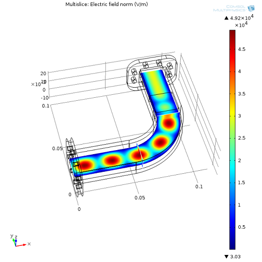
We pass electromagnetic waves in through one end of the waveguide (the end farthest away from the dielectric block) via a power source of 100 watts. The waves oscillate at 10 GHz and move along the rectangular waveguide, around the bend, and then come in contact with the insulator before exiting our model through the other end.
Note that the waveguide in our model is assumed to continue ad infinitum.
We want to figure out how the waveguide and block heat up over time.
We can solve this in two stages using COMSOL Multiphysics and the RF Module:
- Electromagnetics
- Thermal
Let’s fast forward to the results.
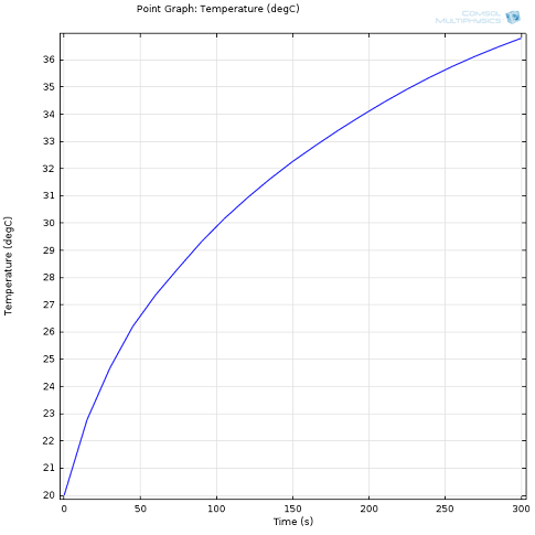
First, we want to find out how the waveguide heats up after turning on the power source.
Next, we can study the electromagnetic fields and temperature for a steady-state solution after the assembly has reached thermal equilibrium. Via the “View” node in the Model Builder, we can hide geometric entities. By hiding the top two layers of the waveguide, we’ll get a much clearer picture of what’s going on inside:
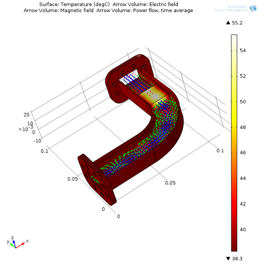
Inside the waveguide: The temperature of the dielectric block as well as the electric (red arrows) and magnetic fields (green arrows) and power flow (blue arrows) are displayed.
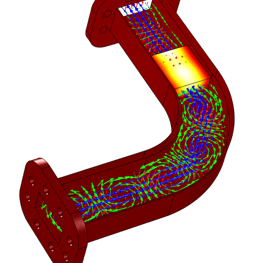
Here’s a closer look at the magnetic fields and dielectric block:
We can also study the electromagnetic fields before and after heating up.
Before heating:
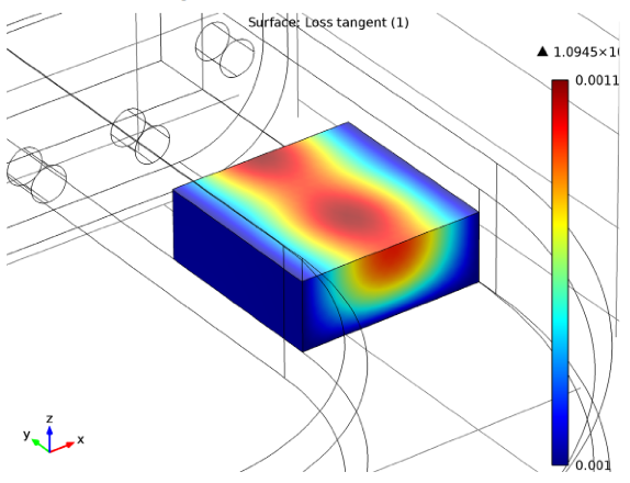
The block’s material properties are functions of temperature, so when it heats up, the electric properties change. Below, the loss tangent in the block is plotted for the steady-state solution. The nonuniform loss tangent distribution is the result of a nonuniform temperature distribution.
Learn How to Build this Model
You can model RF and microwave heating with COMSOL Multiphysics and the RF Module. The model featured here can be downloaded either through the software (via the RF Model Library, under “Microwave Heating”) or the Model Gallery.
Note that the model can be opened with the geometry, mesh, materials, and such pre-loaded, but you will still need to go through the solution steps. In other words, if you’re following the model documentation, you can skip all the steps except for compute.


Comments (4)
Osa Igbinosun
January 9, 2019Is the microwave heating module in COMSOL specifically for a waveguide? If not, can it be amended to describe heating in a waveguide?
Fanny Griesmer
January 9, 2019Hello Osa,
The tutorial model featured here shows you how to model RF heating in a waveguide: https://www.comsol.com/model/rf-heating-6078
To see what else you can model with the RF Module, please go to the product page: https://www.comsol.com/rf-module
Dragos Constantin
January 12, 2019Hi Fanny,
I suppose the input power of 100W used in the model is the average power of the RF power source. In other words, if I have a pulsed power source, the power I have to specify in COMSOL when I define port characteristics is the source peak power times the duty cycle, which is the average power. Is this correct?
Thanks,
Dragos
Brianne Costa
January 15, 2019Hello Dragos,
Thank you for your comment.
For questions related to your modeling, please contact our Support team.
Online Support Center: https://www.comsol.com/support
Email: support@comsol.com