Characterization of an Open GTEM Cell with the COMSOL Multiphysics® Software
Introduction: The Gigahertz Transverse Electromagnetic (GTEM) cell is a fundamental tool for calibration purposes and for studies on Electromagnetic Compatibility (EMC), being able to emulate an incident plane wave (TEM mode) on equipment under test in the GHz frequency band. This chamber is obtained by replacing one port of a two-port TEM cell with a wideband, non-tapered, resistor/wave absorber termination [1], which reduces the excitation of TE and TM modes at high frequencies. The resonances of the non-transverse field components can be further avoided by considering an open GTEM cell [2], derived from a conventional GTEM cell by mechanically removing the sidewalls. With the aid of the COMSOL Multiphysics® simulation software, we have analyzed the electromagnetic behavior of an existing open GTEM cell at different operating frequencies, investigating where the field was most purely TEM.
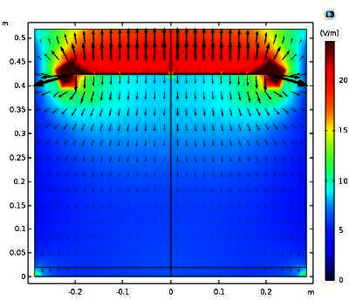
COMSOL Multiphysics® model: In principle, the GTEM cell can be considered as an extension of a 50-ohm transmission line, where the outer conductor is expanded pyramidally, while the central conductor (the GTEM septum) is a thin, wide conductive plate terminated by a combination of resistors and RF absorbers. Using the RF module of the COMSOL Multiphysics® software, we have created a realistic model of the our commercial GTEM cell having an overall length L = 2.78 m, width W = 1.09 m and height H = 1 m (Fig. 1). The 50-ohm broadband resistive network between the septum and the GTEM backwall has been simulated by properly imposing a Transition Boundary Condition (TBC) on a Copper layer with fixed dimensions. On the other hand, the RF absorbers of the real GTEM cell have been faithfully reproduced as arrays of pyramidal lossy structures made of radiation-absorbent material (RAM) [3]. Finally, by exploiting the field symmetries characterizing the model, a Perfect Magnetic Conductor (PMC) condition has been introduced on the longitudinal plane highlighted in Fig. 1, and the model has been solved only for half of the geometry, leading to a significant reduction of the computational time.
Results: The designed COMSOL model has been computed for different values of frequencies: from 250 MHz to 1 GHz with steps of 50 MHz, and from 1 GHz to 3 GHz with steps of 200 MHz. At each frequency value, the TEM behavior in our cell was analyzed on the probing transversal plane highlighted in Fig. 1, where the electric and magnetic fields were computed. Furthermore, to estimate the purity of the propagating TEM mode, the axial ratio has been visualized in post-processing. Finally, the values of Voltage Standing Wave Ratio (VSWR) on the GTEM port provided by COMSOL at different simulation frequencies and those obtained measuring the real GTEM with a Vector Network Analizer have been compared, showing a good agreement between the numerical and experimental results.
References:
[1] D. Konigstein and D. Hansen, “A New Family of TEM-cells with Enlarged Bandwidth and Optimized Working Volume”, Proceedings of the 7th International Zurich Symposium on Electromagnetic Compatibility, pp. 127-130, Zurich, 1987.
[2] R. Rambousky and H. Garbe, “Analysis of Open TEM-Waveguide Structures”, Ultra-Wideband, Short-Pulse Electromagnetics 10, pp. 49-58, Springer, New York, 2014.
[3] “Modeling of Pyramidal Absorbers for an Anechoic Chamber”, COMSOL Multiphysics.
Download
- de vita_poster.pdf - 0.68MB
- de vita_paper.pdf - 0.9MB
- de vita_abstract.pdf - 0.23MB