
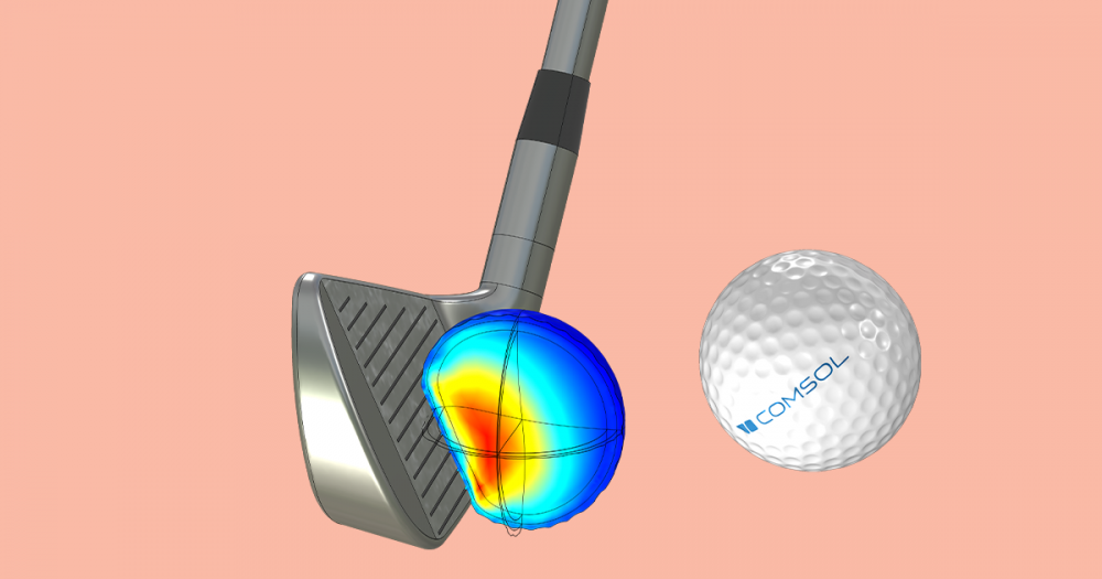
Damage occurs in bearings, gears, rails, and cams due to a damage mechanism called contact fatigue. This happens in assemblies when two parts in contact experience a time-dependent contact pressure. When the transferred load is too high, and after numerous load cycles, a piece of the surface material can flake off and leave a small crater. This phenomenon is called spalling or pitting. With the COMSOL Multiphysics® software, we can model contact fatigue and predict failure in these components.
About the Contact Fatigue Damage Mechanism
Contact fatigue occurs when a changing contact pressure between two parts introduces a time-dependent stress state on both the surface and subsurface level. When stresses are too high, a microcrack forms in the component, either on or under the surface. A subsurface microcrack frequently originates at some kind of defect, such as a material impurity. This microcrack grows parallel to the surface with subsequent loading. At some point, it kinks toward the surface, removing a piece of the material and leaving a shallow hole.
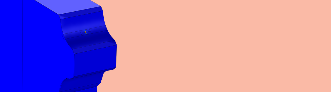
The stress history when a rolling element travels along a curved raceway. The top surface shows high levels of contact pressure in red and stress-free areas in blue. The subsurface level displays high and low equivalent stress in red and blue, respectively.
The three main types of contact fatigue are:
- Standing contact fatigue
- Rolling contact fatigue
- Fretting contact fatigue
In standing contact fatigue, the two objects in contact experience a relative movement in the surface’s normal direction. The movement can be very small, not visible to the human eye, or large with surface separation. The two objects are repeatedly pressed together and then released. In rolling contact fatigue, the contact fatigue is caused by an object rolling across a surface.
We won’t go into the specifics of modeling fretting fatigue in this blog post, but this type of fatigue occurs when the two objects in contact have a small relative motion along the surface, such as vibration. It might seem that the two objects move in phase on the macroscopic level, but the two surfaces can experience relative motion on the microscopic level, which leads to a fatigue failure.
Modeling Contact Fatigue in COMSOL Multiphysics®
We can model contact fatigue in COMSOL Multiphysics using two methods. One way is to create a Contact Pair at the interface between the two objects. Both objects must be modeled and a fine mesh must be applied along the two contact interfaces. This type of contact simulation is often computationally expensive.
The other way to simulate contact fatigue is to use the classical solutions associated with Hertz for contact between two elastic bodies with curved surfaces, which is described in the study of contact mechanics. One of the objects in contact is replaced by an analytical solution for the contact pressure, which is prescribed on the surface of the other body. We can do this by:
- Specifying the contact characteristics, such as the maximum pressure and contact axes, as parameters in the Parameters node
- Expressing the contact pressure at a given location on the surface as a variable in the Variables node
- Prescribing the contact pressure as a boundary load on the surface of the other body
By doing so, we don’t need to model one of the objects, which reduces the model size. Since an accurate resolution of the resulting stress state requires a fine mesh, any technique that reduces the model size is important in contact fatigue modeling.
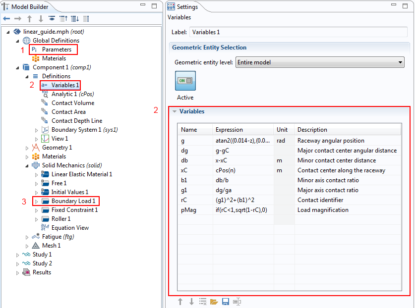
Settings for prescribing an analytical solution for the contact pressure on an object in contact.
The second technique is employed in two tutorial models available in the Application Library of the Fatigue Module: Standing Contact Fatigue and Rolling Contact Fatigue in a Linear Guide. In the first example, a spherical indenter is repeatedly pressed and released over the tested material. In the second, a spherical rolling element moves along a raceway groove.
The characteristic geometric length in both models is a few millimeters, which corresponds to the radius of spherical objects in contact. The characteristic length of the contact area is about a tenth of that measurement. In the standing contact fatigue example, the radius of the indenter is 7 mm and the contact radius is 260 μm. For the rolling contact fatigue example, the radius of the rolling element is 2 mm and the two contact ellipse axes are 161 μm and 36 μm, respectively.
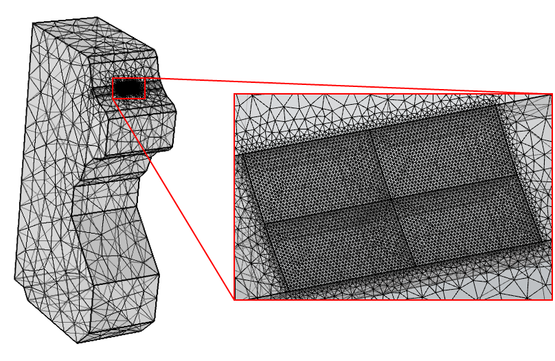
There is a large difference in mesh size between that of the contact surface and the rest of the model.
The contact surface is not the only place where a fine mesh is required. Although the highest contact stress is transferred through this small contact area, the highest equivalent and shear stresses, both used in fatigue analysis, are found on the subsurface level close to the surface. In the standing contact fatigue model, the highest equivalent stress and shear stress are located about 110 μm below the surface. In the rolling contact fatigue example, the maximum of both stress components is found about 20 μm below the surface. This is about 1% of the characteristic length of the geometrical objects, requiring a fine mesh through the depth.
The load transfer is concentrated at one location in standing contact fatigue, while the contact area travels in rolling contact fatigue. We must therefore use a material volume with a fine mesh along the entire path of the traveling object when modeling rolling contact fatigue. In some models, the size of the modeled volume can be reduced, since the contact stress only has a significant influence on the material volume within a few contact lengths from the contact point. In fatigue simulations, the stress state that is further away is insignificant.
By prescribing the contact pressure a few contact lengths before the evaluation point and then moving it to a few contact lengths after this point, we can obtain good results for the center. When modeling rolling contact fatigue, we apply the contact load to about three contact lengths before the evaluation point and then translate it to about three contact lengths after the point. Once we get the results for the center, we can use them in subsequent fatigue studies.
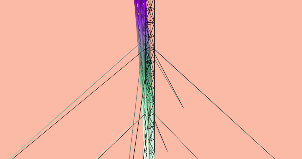
The affected volume around a traveling contact pressure. The top surface displays contact pressure. The bottom volume shows the shear stress in blue for high negative values, red for high positive values, and green for stress-free regions.
Evaluating Contact Fatigue with the Dang Van Model
Once a steady-state load cycle is computed, we can base the fatigue evaluation on one of the models included with the Fatigue Module. The Dang Van model, for example, is frequently used for compressive load cases because it can take the influence of the compressive state into account. Moreover, the model parameters can be easily extracted from the standard pure tension and pure torsion fatigue tests. The Dang Van model is the latest extension of the Fatigue Module and is new with COMSOL Multiphysics® version 5.2a.
Learn More About How to Model Contact Fatigue
- Try it yourself: Download the tutorials featured in this blog post
- Read more about the new Dang Van model on the 5.2a Release Highlights page

Comments (1)
Josh Thomas
March 11, 2022Hi Mateusz,
I am interested in modeling fretting fatigue due to vibration in COMSOL. Does COMSOL support this type of modelling?
Thanks,
Josh Thomas
AltaSim Technologies