
Simulating Tensile Stress in a Tube Connection with Prestressed Bolts

When analyzing a bolted joint, one thing to consider for an accurate analysis is the bolt pretension. With COMSOL Multiphysics, the effects of prestressing a bolt can be easily computed using the Bolt Pre-tension feature available in the Structural Mechanics Module. After modeling prestressed bolts, a further analysis can then be conducted on an external load applied to the structure. Here, we will explore how to include prestressed bolts in a tube connection model, and then carry out a stress analysis on the connection.
The Physics of a Bolted Joint
Bolts are pretensioned by tightening them until they are snug, then using a wrench to further torque the bolt. Since the bolt head is tight against the washer or flange’s surface, turning the bolt farther causes it to elongate slightly. The elongated bolt functions as a sort of stretched spring, pulling the two surfaces in the connection together. Other terms that you might recognize that refer to prestressed bolts include pretension, preload, and clamp load.
When a bolt is properly prestressed, it is able to carry a heavier load than an improperly stressed bolt, or one that has not been prestressed at all. This is because of the way in which a pretensioned bolt carries a direct load; the load is distributed over the connected surfaces around the bolt, and the bolt only sustains a small part of the load. Additionally, because the bolt has been stretched to a certain predetermined value, the bolt will not loosen over time. However, in a bolt that has not been prestressed, all tensile load will be carried by the bolt itself.
If a shear load is applied to a properly designed bolted connection, then the transverse force is transmitted by friction between the surfaces pressed together by the bolt pretension. This is a much more efficient way to carry a shear load than one that is carried only by the bolts themselves. There are handbook formulas for designing bolted connections, but for more complicated geometries a finite element analysis is often required for a safe design. Additionally, the stresses induced around the bolt holes may influence the analysis results.
Simulating Bolt Pretension with COMSOL Multiphysics
In COMSOL Multiphysics, the prestress in bolts can be modeled using the Bolt Pre-Tension feature in the Solid Mechanics physics interface in the Structural Mechanics Module. From here, you can select the Pre-tension type (in this case, Pre-tension stress) and enter the stress in the σp edit field. For each individual bolt, you add one Bolt Selection subnode. In this feature, each bolt is described by selecting one or more boundaries that define a cross section through it. Results, such as the axial bolt force, bolt shear force, and predeformation will then be available for all bolts.
Analyzing Tensile Stress in a Tube Connection
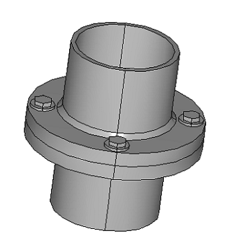
Using the Prestressed Bolts in a Tube Connection model, we can explore the use of the Bolt Pre-Tension feature and how to compute the effect of prestress and external loads in a tube connection. In the model, the tube is made of steel with an outer diameter of 220 mm and an inner diameter of 200 mm. The flanges are connected by four bolts prestressed to 75% of their yield strength. The external load is a bending moment on the pipe. The geometry is depicted below:

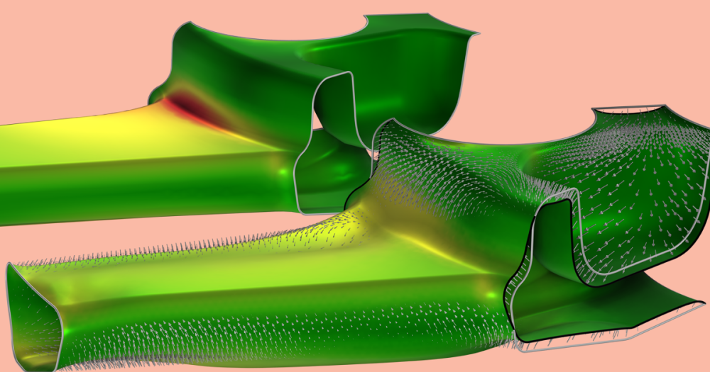
Because of model symmetry, only half of one side of the flange needs to be analyzed. There are two contact regions modeled; one between the bottom surface of the flange and a fixed solid that acts as a symmetry condition, and the second between the washers under the bolt head and the flange. After adding pretension to the bolts, there is tensile stress in the bolt and a compressive stress in the surrounding part of the flange, as shown in the figure below.

The tensile stress after the pretension step.
When the maximum load is applied to the tube, a stress of around 300 MPa develops in the fillet between the flange and tube. The bending causes the bolt on the tensile side to deform, and the deformation and stress profile are no longer symmetric. The bolt is exposed to a non-uniform distribution of stress over the cross section, and the maximum stress rapidly increases from 75% of the yield stress (the prestressed value) to 88% of the yield stress. In the graph below (right), it can be seen how the applied external load rapidly increases the force in one of the bolts, showing that it is not operating properly.
")
|

|
| Equivalent stress at the maximum external load. The deformation is exaggerated. | The bolt forces as a function of the external load. |
By comparing the contact pressure between the flanges just after prestressing the bolts to the contact pressure after the final maximum load has been applied, a clear shift in the contact pressure distribution can be seen. This indicates that there are not enough bolts in the connection.
")
|
")
|
|
Contact pressure between flanges after pretensioning the bolts. |
Contact pressure between the flanges at full external load. |
Model Download
- Download the Prestressed Bolts in a Tube Connection model from the Model Gallery.

Comments (0)